Glass tube for fluorescent lamp, fluorescent lamp, and lighting system

A technology for fluorescent lamps and glass tubes, applied in discharge lamps, low-pressure discharge lamps, gas discharge lamps, etc., which can solve the problems that the strength of the bulb glass is not improved, and it is difficult to realize the thinning of the bulb, and achieve the effect of easy processing and difficult damage

Inactive Publication Date: 2011-05-11
PANASONIC CORP
View PDF0 Cites 3 Cited by
  • Summary
  • Abstract
  • Description
  • Claims
  • Application Information

AI Technical Summary

Problems solved by technology

[0008] However, when a fluorescent light bulb was produced by the above-mentioned method, it was found that the glass strength of the bulb was not improved even though a film made of a metal oxide and a film made of a hydrophobic lubricant were formed on the surface of the light bulb.
Therefore, it is difficult to achieve thinning of the bulb

Method used


Image

  • Glass tube for fluorescent lamp, fluorescent lamp, and lighting system
  • Glass tube for fluorescent lamp, fluorescent lamp, and lighting system
  • Glass tube for fluorescent lamp, fluorescent lamp, and lighting system

Examples


Embodiment Construction

[0047] A glass tube for a fluorescent lamp (hereinafter simply referred to as a “glass tube”), a fluorescent lamp, and a lighting device according to an embodiment of the present invention will be described below based on the drawings.

[0048] [Structure of glass tubes, fluorescent lamps and lighting fixtures]

[0049]

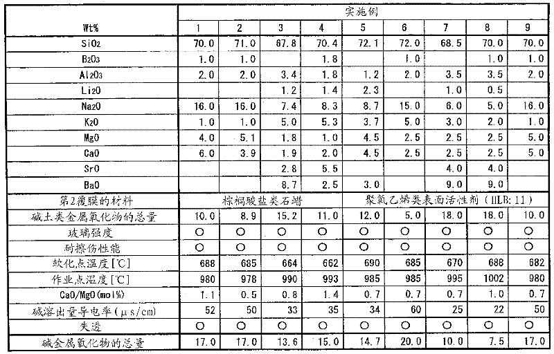
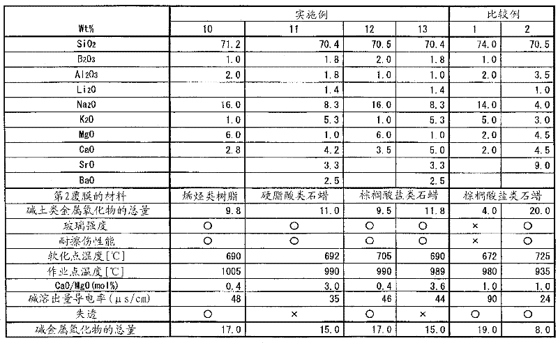
[0050] The glass tube of the present invention is composed of a tube body, a first coating formed at least on the outer peripheral surface of the tube body, and a second coating laminated on the first coating.

[0051] The pipe body preferably has a wall thickness t [mm] and an outer diameter φ [mm] satisfying the relationship of t≤0.7 or t / φ≤0.42. In particular, 0.4≦t≦0.6 and 1≦φ≦10 are preferable.

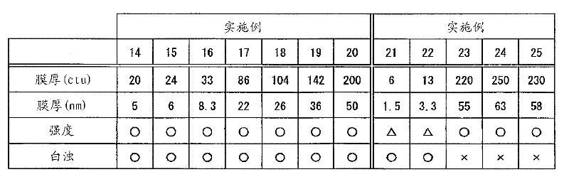
[0052] The thickness of the first coating is preferably 5 to 100 nm, more preferably 5 to 50 nm. image 3 It is a graph showing the test results related to the influence of the film thickness of the first film on the glass strength and clouding of the glass ...


PUM

PropertyMeasurementUnit
softening pointaaaaaaaaaa
melting pointaaaaaaaaaa
thicknessaaaaaaaaaa

Abstract

Disclosed is a glass tube for a fluorescent lamp that can realize a reduction in thickness of a bulb of a fluorescent lamp. The glass tube for a fluorescent lamp comprises a tube body formed of a glass comprising 60 to 75 wt% of silicon oxide and 5 to 18 wt% of an alkaline earth metal oxide, a first film that is formed at least on the outer peripheral face of the tube body and is formed of at least one oxide selected from tin oxide, titanium oxide, zirconium oxide, and silicon oxide, and a second film that is stacked on the first film and is formed of a hydrophobic lubricant or a surfactant having an HLB value of not more than 13.

Description

technical field [0001] The present invention relates to a glass tube for a fluorescent lamp, a fluorescent lamp and a lighting device. Background technique [0002] In recent years, from the viewpoint of protecting the global environment, resource conservation and reduction of CO 2 emissions. Just in the field of fluorescent lamps for saving resources and reducing CO 2 In terms of emissions, it is conceivable to make glass bulbs (hereinafter referred to as "bulbs") thinner. That is, by reducing the wall thickness of the glass bulb, the amount of glass used as the material of the bulb can be reduced, so that resource saving can be realized. In addition, by reducing the amount of glass used, the amount of gas consumed by the melting furnace during glass production is also reduced, so CO2 can also be achieved. 2 reduction in emissions. [0003] However, it can be predicted that once the wall of the bulb is thinned, the strength of the glass will decrease. Therefore, it is...

Claims


Application Information

Patent Timeline
Patent Type & Authority Applications(China)
IPC IPC(8): H01J61/35C03C3/085C03C3/091C03C17/245C03C17/42H01J61/30
CPCH01J61/302C03C3/087C03C3/091C03C17/42C03C2217/76H01J61/35H01J61/70
Inventor 元家淳志北嘉之谷内昭
Owner PANASONIC CORP
Why Eureka
Try Eureka