Fluorescent lamp made of glass and having particular composition

a technology of glass and fluorescence lamp, which is applied in the field of fluorescent lamps, can solve the problems of not describing the optimal amount of added elements, and the ratio of rare earth elements, and achieve the effects of preventing solarization, and improving the physical strength of glass

Inactive Publication Date: 2012-01-10
PANASONIC LIQUID CRYSTAL DISPLAY CO LTD
View PDF6 Cites 5 Cited by
  • Summary
  • Abstract
  • Description
  • Claims
  • Application Information

AI Technical Summary

Benefits of technology

[0044]The present invention can provide glass which is excellent in terms of the physical strength, heat resistance, prevention of solarization, and the properties for blocking ultraviolet rays when an appropriate amount of such elements as B2O3, TiO2, CeO2 and Fe2O3 is added. Furthermore, when a rare earth element, such as Gd or Yb, is added, the physical strength of the glass can further be increased.
[0045]Glass tubes using the glass for fluorescent lamps according to the present invention are excellent in terms of the physical strength, heat resistance, prevention of solarization, and the properties for blocking ultraviolet rays, and have excellent effects of preventing scratching during the process for manufacturing glass tubes and fluorescent lamps, and thus the workability and productivity are higher.

Problems solved by technology

However, these gazettes do not describe any optimal amount for the added elements, nor any ratio for rare earth elements to be contained.

Method used


Image

  • Fluorescent lamp made of glass and having particular composition
  • Fluorescent lamp made of glass and having particular composition
  • Fluorescent lamp made of glass and having particular composition

Examples


first embodiment

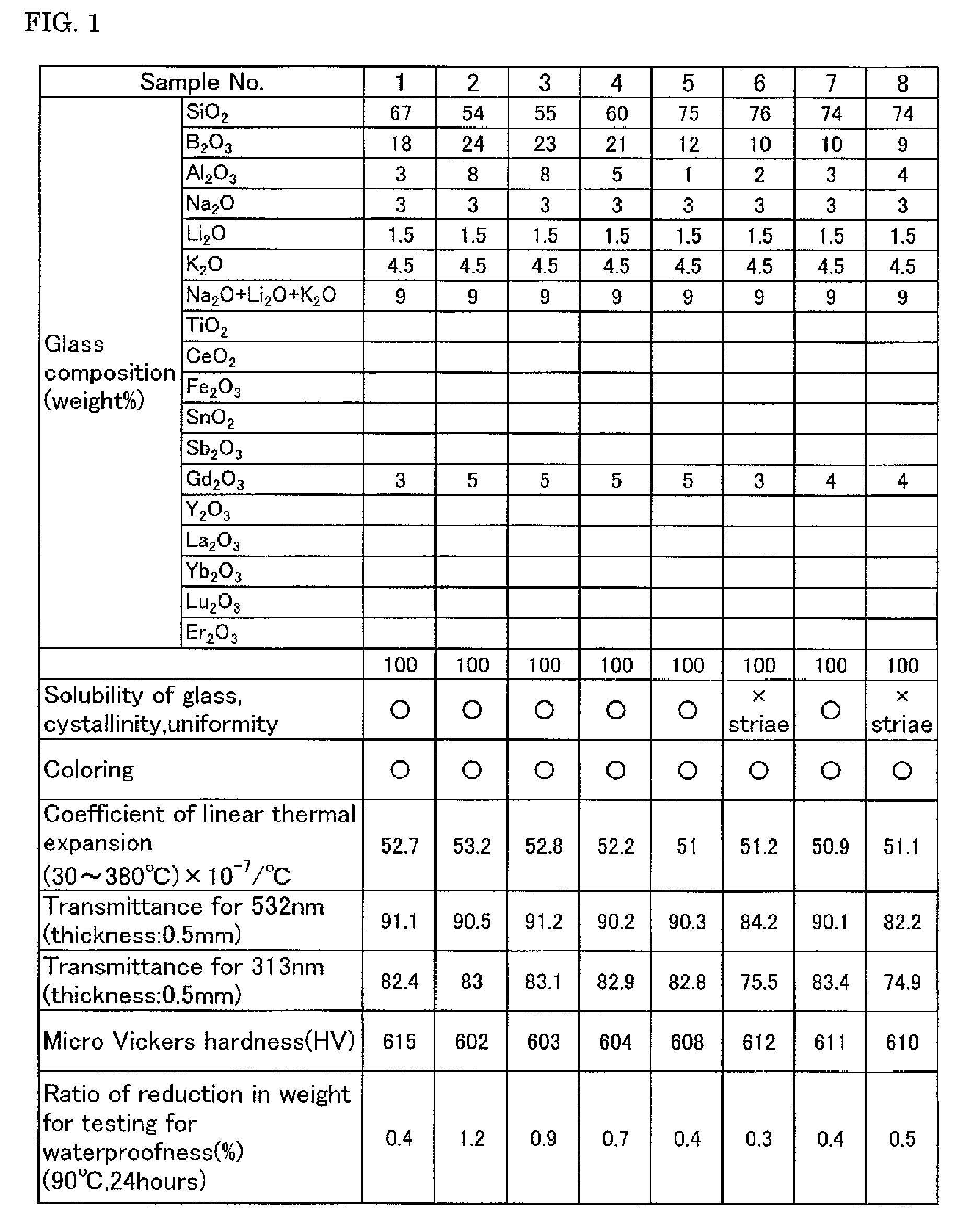
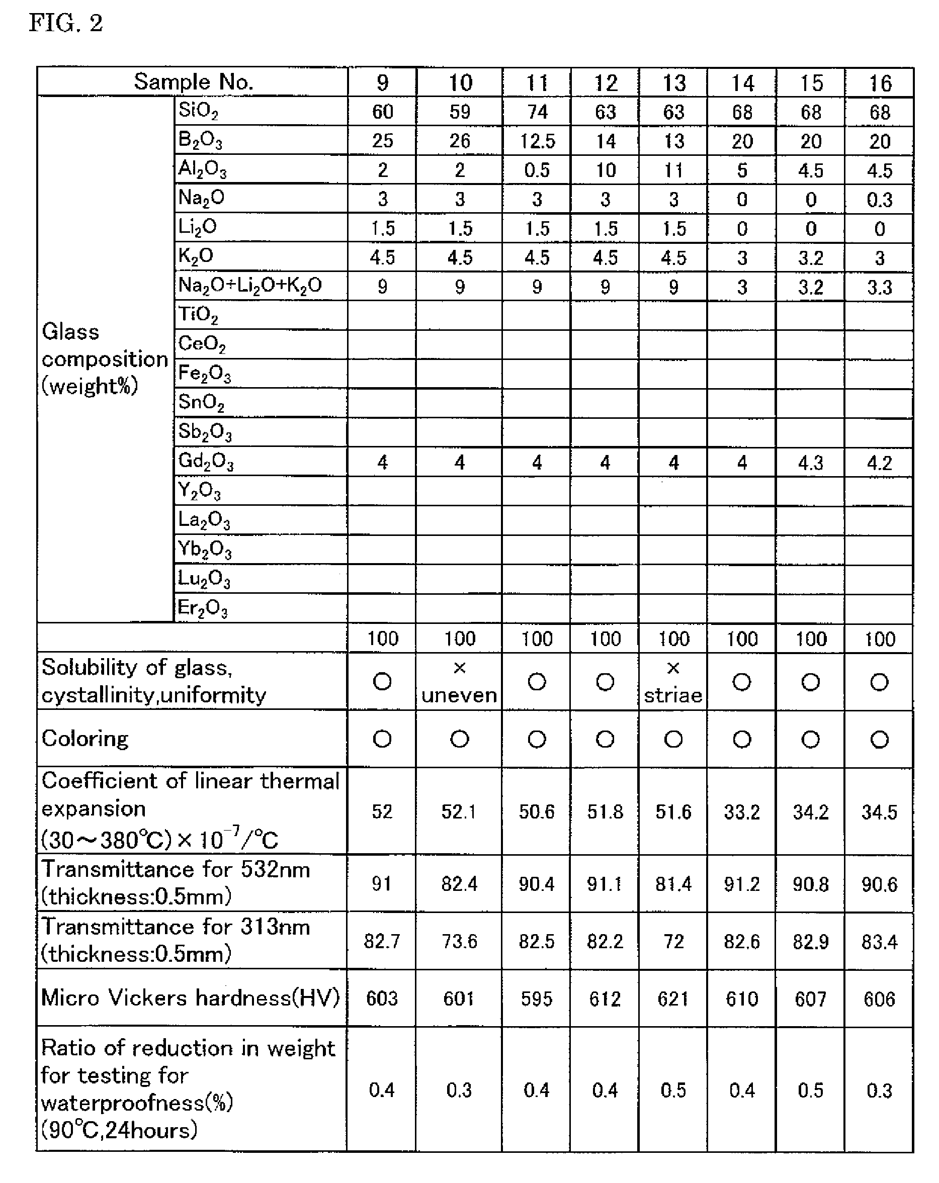
[0079]Next, detailed examples where the glass composition of the glass for fluorescent lamps according to the present invention is examined are given. The tables in FIGS. 1 to 6 show the composition of the examined glass and the results of evaluation of the properties. FIGS. 1 to 6 show the properties for 46 samples. From among these samples, Nos. 2, 6, 8, 10, 11, 13, 14, 18, 20, 22, 24, 28, 31, 35, 45 and 46 are shown as comparative examples, and the rest are according to the present embodiment.

[0080]In the present invention, the solubility of the glass, the crystallinity, the uniformity, the color, the coefficient of linear thermal expansion, the transmittance, the micro Vickers hardness, and the ratio of reduction in weight after the test for waterproofness were evaluated as the properties of the glass for fluorescent lamps.

[0081]Glass was prepared in the following manner. A glass material powder having the composition shown in the tables in FIGS. 1 to 6 was weighed, put in a cru...

second embodiment

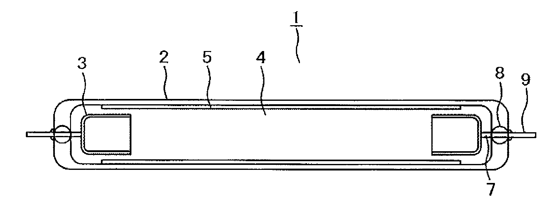
[0110]FIG. 8 is a schematic cross sectional diagram showing the configuration of the fluorescent lamp 1 according to the present invention.

[0111]The fluorescent lamp 1 is provided with a pair of electrodes 3 in cup form which face each other at the two ends inside a glass tube 2 made of a light transmitting insulating material, and openings at the two ends of the facing electrodes 3 in cup form face the main discharge region. Furthermore, a neon-argon (Ne—Ar) gas and mercury are sealed in the glass tube 2 as an inert gas 4 after making the inside of the glass tube 2 a vacuum, and thus, a fluorescent lamp is formed. A fluorescent body film 5 is deposited on the inner wall surface of the glass tube 2. In addition, the pair of electrodes 3 in cup form can be formed of a material having tungsten (W) as a main component, for example.

[0112]Next, the electrodes 3 in cup form are described in detail in reference to FIGS. 9A and 9B. FIG. 9A is a schematic, longitudinal cross sectional diagra...

third embodiment

[0119]FIG. 10 is an exploded cross sectional diagram showing a liquid crystal display device using a fluorescent lamp 1 where the glass described in the first embodiment is used. FIG. 10 shows a liquid crystal display device used in relatively large scale display devices, such as TVs. It is necessary for TVs to have a highly bright screen, and therefore, liquid crystal display devices having a so-called directly-behind-the-screen type backlight are used, so that the number of light sources is great.

[0120]In FIG. 10, the liquid crystal display device is separated into a liquid crystal display panel and a backlight. The liquid crystal display panel has a structure where a liquid crystal layer is sandwiched between a TFT substrate 10 on which thin film transistors (TFTs), pixel electrodes, scan lines, video signal lines and the like are formed, and a facing substrate 20 on which color filters are formed. In addition, a lower polarizing plate 11 adheres to the bottom of the TFT substrat...


PUM

PropertyMeasurementUnit
lengthaaaaaaaaaa
lengthaaaaaaaaaa
thicknessaaaaaaaaaa

Abstract

An object of the present invention is to provide fluorescent lamps used as a light source for liquid crystal display devices, which have excellent characteristics in terms of preventing solarization, the properties for blocking ultraviolet rays, and the physical and thermal strength, and preventing scratching. The present invention provides fluorescent lamps made of glass containing 55.0% to 75.0% of SiO2; 10.0% to 25.0% of B2O3; 1.0% to 10.0% of Al2O3; 0% to 3.8% of Na2O; 0% to 3.0% of Li2O; 3.0% to 10.0% of K2O; 3.2% to 16.0% of Na2O+Li2O+K2O; 0.5% to 8% of TiO2; 0.1% to 5% of CeO2; 0.6% to 8.1% of TiO2+CeO2; 0.001% to 0.05% of Fe2O3; 0% to 0.7% of Sb2O3; 0.1% to 3.0% of SnO2; and 0.5% to 10.0% of at least one rare earth element selected from the group consisting of Gd, Y, La, Yb and Lu by weight, and is characterized in that the coefficient of linear expansion in a temperature range of 30° C. to 380° C. is 34×10−7 / ° C. to 58×10−7 / ° C.

Description

[0001]The present application claims priority over Japanese Application JP 2008-115045 filed on Apr. 25, 2008, the contents of which are hereby incorporated into this application by reference.BACKGROUND OF THE INVENTION[0002](1) Field of the Invention[0003]The present invention relates to a fluorescent lamp and, in particular, to a fluorescent lamp for use for a backlight source for display devices, such as liquid crystal displays, glass for fluorescent lamps which is appropriate for fluorescent lamps, and a glass tube using the same.[0004](2) Related Art Statement[0005]Liquid crystal display devices widely used in televisions and monitors have a backlight made up of optical members, such as a light source provided on the rear or side of the liquid crystal display portion, a reflective sheet for making light emitted from the light source uniform, a light guide plate, a diffusion sheet and a prism sheet, and illuminate the liquid crystal display portion from the rear, so that images ...

Claims


Application Information

Patent Timeline
Patent Type & Authority Patents(United States)
IPC IPC(8): H01J17/16C03C3/089
CPCC03C3/095C03C4/085H01J61/302
Inventor HOSHIMURE, TAKASHIASANO, TETSUOYAMAMOTO, HIROKINAITO, TAKASHI
Owner PANASONIC LIQUID CRYSTAL DISPLAY CO LTD
Why Eureka
Try Eureka