Main shaft device for numerical controlled gear hobbing machine

A technology of spindle device and gear hobbing machine, which is applied in the direction of gear tooth manufacturing device, gear cutting machine, and components with teeth, etc. It can solve the problems of long tool setting time, reduced spindle precision, easy wear of bearings, etc., and achieve high work efficiency and precision Excellent retention and high spindle accuracy

Active Publication Date: 2011-05-18
齐重数控装备股份有限公司
View PDF6 Cites 37 Cited by
  • Summary
  • Abstract
  • Description
  • Claims
  • Application Information

AI Technical Summary

Problems solved by technology

[0002]The main shaft of the existing gear hobbing machine in my country mostly adopts the sliding bearing structure, because this kind of bearing is particularly easy to wear during use, which often leads to the reduction of the precision of the main shaft and poor retention Hobbing machines cannot withstand heavy cutting conditions
In addition, the tool change of the main shaft of the existing gear hobbing machine is generally manually operated. When changing the tool bar and hob of different specifications, it is first necessary to manually loosen the lock n...

Method used


Image

  • Main shaft device for numerical controlled gear hobbing machine
  • Main shaft device for numerical controlled gear hobbing machine
  • Main shaft device for numerical controlled gear hobbing machine

Examples


example 1

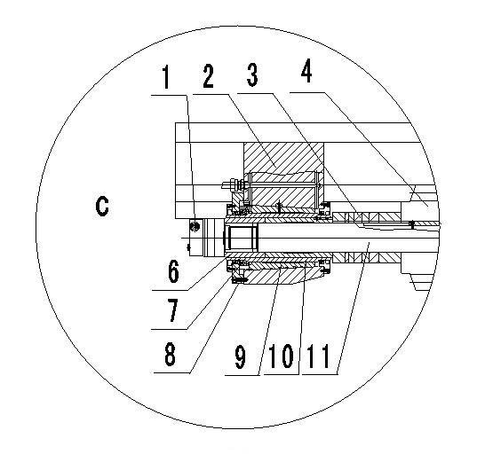
[0023] Such as figure 1 As shown, the main shaft mechanism of the CNC gear hobbing machine of the present invention includes a tool bar assembly, a tool bar assembly clamping mechanism and a tool change mechanism, wherein the structure of the tool bar assembly is: the hob 4 is fixed on the middle part of the tool bar 11 through a flat key 12, and Its two sides are equipped with adjusting pad 3, the shaft sleeve 6 is installed on the left side of the adjusting pad 3, the left end of the knife rod 11 is equipped with a lock nut 1, the right end has a keyway, and the tail end of the taper handle is equipped with a knife rod Rivet 4.

example 2

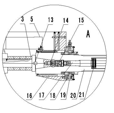
[0025] Such as figure 2 As shown, the clamping mechanism of the tool bar assembly is: a keyway is provided on both sides of the left end surface of the main shaft 20, a square key 13 matching the keyway at the right end surface of the tool bar 11 is housed in the keyway, and a valve is housed in the inner hole of the main shaft 20. Claw assembly 15 , the valve claw hook in the valve claw assembly 15 corresponds to the cylindrical boss of the knife bar pull stud 14 .

[0026] The main shaft centering and positioning mechanism includes a rear static pressure shoe 16 on the left side in the cylindrical hole at the right end of the hob body 5 and a two-way thrust roller bearing 8 on the right side. The left end of main shaft 20 passes in rear static pressure pad 16 cylindrical holes, and the left side of bidirectional thrust roller bearing 18 pushes on the shaft shoulder of main shaft 20 left parts.

example 3

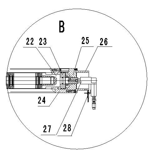
[0028] Such as image 3 As shown, the structure of the tool changing mechanism is; the valve claw assembly 15 is threadedly connected with the left end of the pull rod 17, and the right end of the pull rod 17 is threaded with the piston rod 22; Disc spring 21 is arranged; Oil cylinder body 24 is contained in the afterbody of main shaft 20, and its right end is equipped with flange plate 25, support 26 successively;


PUM


Abstract

The invention discloses a main shaft device for a numerical controlled gear hobbing machine. The main shaft device comprises a cutter bar assembly, a cutter bar assembly clamping mechanism and a cutter changing mechanism, wherein the cutter bar assembly comprises a cutter bar, a hobbing cutter, a cutter regulating pad, an axle sleeve, a locking nut and a cutter bar blind rivet; the cutter bar assembly clamping mechanism consists of a square key and a claw assembly; and the cutter changing mechanism consists of a pull rod, a piston rod, a disc-shaped spring, a hydro-cylinder body, a flange plate, a bracket, a rotary joint and a spacing switch. The main shaft device has the advantages that: a hydrostatic bearing is arranged in the main shaft structure of the high-accuracy numerical controlled gear hobbing machine, so the main shaft device can constantly work under a heavy-load cutting condition; a main shaft has high accuracy and good accuracy retaining ability; and the cutter bar assembly with the hobbing cutter is arranged and set outside a machine in a cutter workshop; the cutter bar assembly is subjected to whole cutter changing on the gear hobbing machine; and the setting assisting time of the hobbing cutter does not occupy the total part machining time of a machine tool, so the whole machine tool has high working efficiency.

Description

technical field [0001] The invention relates to a spindle device of a numerically controlled gear hobbing machine. Background technique [0002] The main shaft of the existing gear hobbing machine in my country mostly adopts the sliding bearing structure. Since this kind of bearing is particularly easy to wear during use, the hobbing machine cannot withstand heavy load cutting conditions due to the reduction of the precision of the main shaft and poor retention. In addition, the tool change of the main shaft of the existing gear hobbing machine is generally manually operated. When changing the tool bar and hob of different specifications, it is first necessary to manually loosen the lock nut on the long pull rod and the nut on the tool bar, and manually loosen the For the long pull rod, remove the cutter rod and hob, install a new cutter rod and hob, and re-tighten the long pull rod and nut. After the hob is replaced, it is necessary to try cutting the processed parts again ...

Claims


Application Information

Patent Timeline
IPC IPC(8): B23F23/00
Inventor 李立强姜辉王伟顺马伟良石志民杜宏祺马蕾张文武娄晓钟沈红忠
Owner 齐重数控装备股份有限公司
Why Eureka
Try Eureka