Novel high-speed electrical desalting and dewatering apparatus

An electric desalination and dehydration, high-speed technology, applied in the direction of electricity/magnetic dehydration/demulsification, etc., can solve the problems of reducing, unable to meet the energy saving and emission reduction, and increasing the power consumption of electric desalination equipment, and achieve the effect of improving the processing capacity.

Inactive Publication Date: 2011-05-18
江苏三星化工有限公司
View PDF10 Cites 9 Cited by
  • Summary
  • Abstract
  • Description
  • Claims
  • Application Information

AI Technical Summary

Problems solved by technology

However, when complex crude oil is processed or the processing conditions change, especially when a stubborn emulsion with high conductivity is formed, in order to protect the power supply equipment, the high voltage output to the electric desalination tank is gradually reduced, and in severe cases, it is often reduced to the point where the emulsification cannot be broken. Degree
That is to say, the traditional 100% full-impedance electric desalination power supply reduces the demulsification, desalination and dehydration effect of the high-voltage electric field in order to protect the transformer power supply equipment when emulsification occurs
Moreover, this 100% full-impedance electric desalination power supply increases the power consumption of the electric desalination equipment during the process of enhancing the demulsification effect by increasing the output, which cannot meet the current energy-saving and emission-reduction requirements of refineries.

Method used


Image

  • Novel high-speed electrical desalting and dewatering apparatus
  • Novel high-speed electrical desalting and dewatering apparatus
  • Novel high-speed electrical desalting and dewatering apparatus

Examples


Embodiment Construction

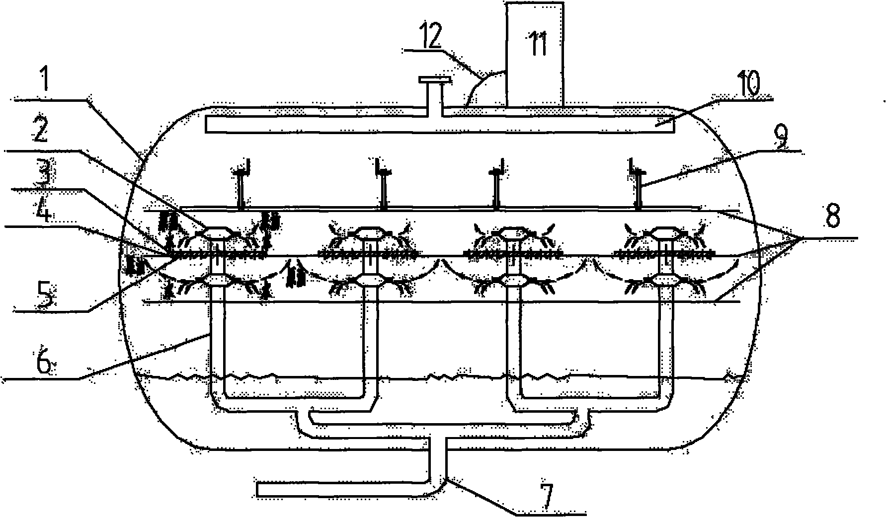
[0018] See attached figure 1 , a layout diagram of parts inside a tank of a new type of high-speed electric desalination and dehydration equipment in this embodiment.

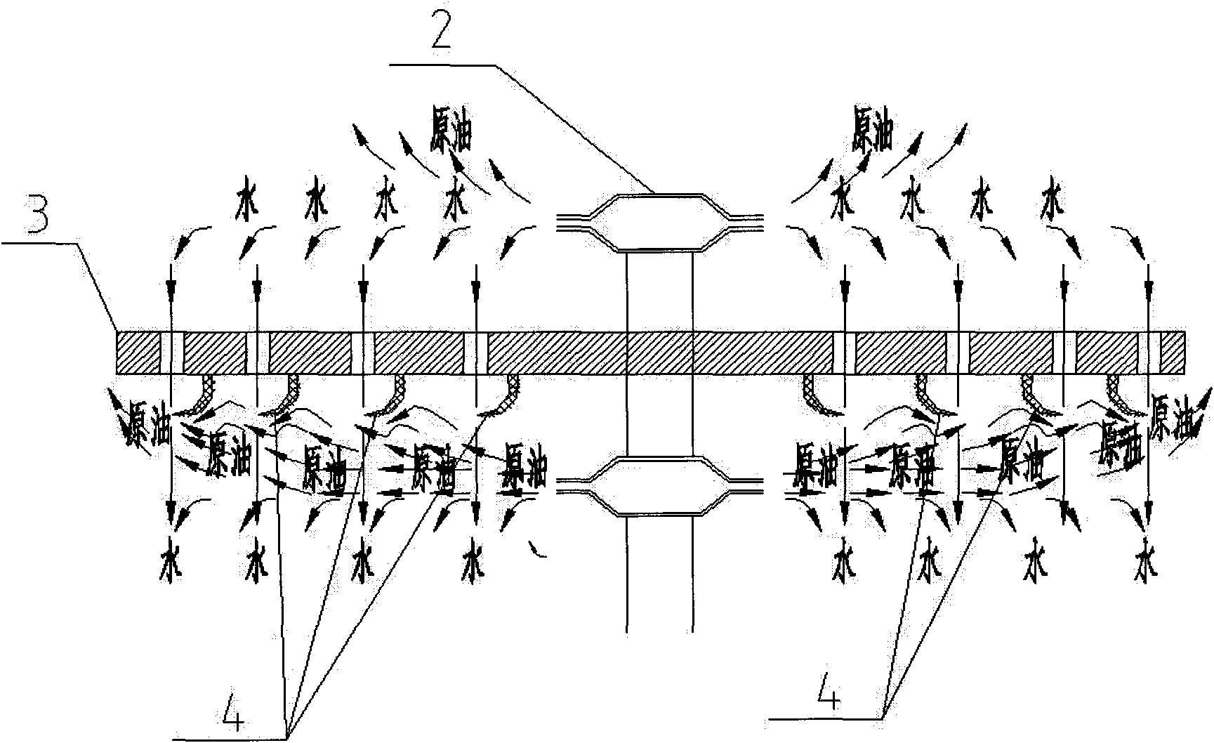
[0019] The crude oil emulsion composed of crude oil, water and demulsifier enters the oil inlet branch pipe (6) in the electric desalination and dehydration tank through the oil inlet main pipe 7 outside the electric desalination and electric dehydration tank (1), and then passes through the inlet pipe (6) designed in the middle of the tank body. The oil injector (2) sprays out, and under the action of a high-voltage electric field, oil-water separation, dehydration and desalination are carried out, and the separated crude oil is collected into the oil discharge collection pipe (10) at the top of the tank, and leaves the tank to complete the desalination process. The separated water settles at the bottom of the tank. When the electric desalination equipment is operating normally, the lower part of the electric ...


PUM


Abstract

The invention relates to a novel high-speed electrical desalting and dewatering apparatus belonging to the technical field of crude oil pretreatment. The apparatus comprises an exclusive transformer for providing high voltage for plate electrodes in an electrical desalting and dewatering tank, at least two layers of horizontal high-voltage plate electrodes, insulating suspensions and inlet oil ejectors, wherein a crude oil flow baffle is designed between every two adjacent inlet oil ejectors, the exclusive transformer connects high-frequency pulse high voltage to the high-voltage plate electrodes in the electrical desalting and dewatering tank by means of a high-voltage electricity introduction bar, and a drain hole is designed on the flow baffle; and a crude oil flow diversion device of which the direction is opposite to the direction of crude oil ejected by the inlet oil ejectors is designed at the lower end of the drain hole, and high-frequency pulse high voltage is output to the high-voltage plate electrodes in the electrical desalting and dewatering tank so as to form high-frequency pulse high-voltage electric field regions among the plate electrodes. The invention can further improve the treatment capacity of the electrical desalting apparatus, and the treatment capacity is increased to 2.0-2.5 times compared with the traditional electrical desalting apparatus. Simultaneously, the invention solves the problems of power failure, tripping, short circuit and the like of the electrical desalting transformer often existing in the process of treating low-quality crude oil, thereby ensuring that the apparatus can smoothly run for a long-time cycle under various working conditions.

Description

technical field [0001] The invention relates to a crude oil desalination and dehydration technology, in particular to a novel high-speed electric desalination and dehydration equipment, which belongs to the technical field of crude oil pretreatment. Background technique [0002] Crude oil is an extremely complex mixture of hydrocarbons. The properties of crude oil produced by different oil fields, different oil regions, and even different oil wells are often different from each other. The water content and salt content in them have adverse effects on the storage, transportation, processing and final products of crude oil. , so desalination and dehydration are required. [0003] The desalting and dehydration of crude oil is generally carried out in two steps. For the first time, dehydration and desalination are carried out in the oil field after the crude oil is extracted, so that the water content and salt content are initially reduced, and then transported out after reachi...

Claims


Application Information

Patent Timeline
Patent Type & Authority Applications(China)
IPC IPC(8): C10G33/02
Inventor 刘建春王洪福
Owner 江苏三星化工有限公司
Why Eureka
Try Eureka