Cantilever-type push-pull boat system for plasma enhanced chemical vapor deposition (PECVD) device

A cantilever type, push-pull boat technology, applied in the direction of transportation and packaging, gaseous chemical plating, metal material coating technology, etc., can solve the problems of affecting the reaction efficiency, affecting the service life of the device, and inaccurate positioning, so as to simplify the conveying system , Improving the conveying efficiency and improving the stability

Inactive Publication Date: 2011-05-18
SOUTH CHINA UNIV OF TECH
View PDF5 Cites 22 Cited by
  • Summary
  • Abstract
  • Description
  • Claims
  • Application Information

AI Technical Summary

Problems solved by technology

[0004] The push-pull boat conveying system of the existing solar silicon wafer processing equipment is simple and practical in structure, and the cost is relatively low. It is widely used in various solar silicon wafer processing devices such as diffusion furnace equipment, but there are also multiple deficiencies: (1 ) It is difficult to adjust the speed by using an AC motor, and it is not suitable for some occasions that need to adjust the speed; (2) The use of V-belt transmission is prone to vibration and relative sliding, which makes the positioning inaccurate, and the vibration will cause damage to the raw materials and affect the service life of the device; ( 3) When the reaction chamber is long and the running distance is l

Method used


Image

  • Cantilever-type push-pull boat system for plasma enhanced chemical vapor deposition (PECVD) device
  • Cantilever-type push-pull boat system for plasma enhanced chemical vapor deposition (PECVD) device
  • Cantilever-type push-pull boat system for plasma enhanced chemical vapor deposition (PECVD) device

Examples


Embodiment

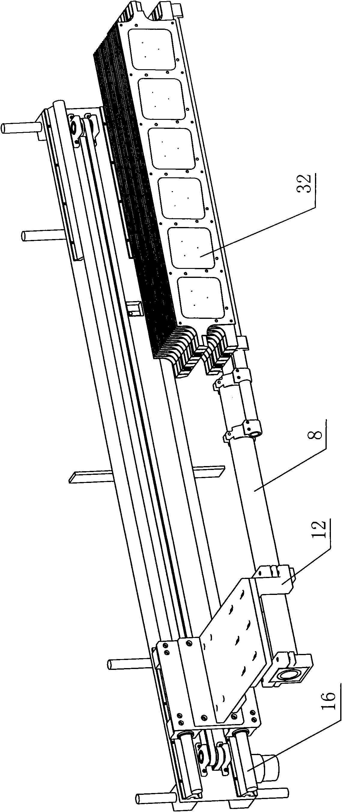
[0031] A kind of cantilevered push-pull boat system used for PECVD equipment in this embodiment, its structure is as follows image 3 As shown, it includes a cantilever rod mechanism, a side connection mechanism and a rolling linear guide bushing auxiliary mechanism. The rolling linear guide bushing auxiliary mechanism used as a cantilever rod mechanism for horizontal movement and vertical motion guidance is set on the frame of the PECVD equipment. The cantilever rod mechanism It is fixed on the side connecting mechanism, which is connected with the auxiliary mechanism of the rolling linear guide bush;

[0032] The specific structure of the cantilever mechanism is as follows: Figure 4As shown, it includes a thick tube 8 and two thin tubes 9, the two thin tubes 9 are arranged side by side, and are connected to one end of the thick tube 8 through the rear connection block 10, and the other end of the thick tube 8 is provided with a thick tube connection Seat 11 and thick tube ...


PUM


Abstract

The invention discloses a cantilever-type push-pull boat system for a plasma enhanced chemical vapor deposition (PECVD) device, comprising a cantilever pole mechanism, a side bindiny mechanism and a rolling linear guide sleeve assistant mechanism, wherein the rolling linear guide sleeve assistant mechanism which is used for guiding the horizontal movement and vertical movement of the cantilever pole mechanism is arranged on the rack of the PECVD device; the cantilever pole mechanism is fixed on the side bindiny mechanism; the side bindiny mechanism is connected with the rolling linear guide sleeve assistant mechanism; the rolling linear guide sleeve assistant mechanism comprises a fixed plate, a horizontal transmission assembly and a vertical transmission assembly; and the horizontal transmission assembly and the vertical transmission assembly respectively control the cantilever pole mechanism to drive raw materials to move horizontally and vertically. The cantilever-type push-pull boat system has the following advantages: a mode that an antilever pole extends into a reaction cavity to take and put a graphite boat is adopted, thus a transmission system is simplified, and the transmission efficiency is improved; a side fixing mode is adopted, thus silicon wafer fragments on the graphite boat can be prevented from falling on the system so as to prevent influence on the normal action of the system; and in addition, the space is saved, and a plurality of push-pull boats can simultaneously move.

Description

technical field [0001] The invention relates to the field of material conveying systems of PECVD devices, in particular to a cantilevered push-pull boat system for PECVD devices. Background technique [0002] The push-pull boat conveying system used for solar silicon wafer processing equipment is an important component of solar silicon wafer processing equipment. It is mainly used to transport raw materials and raw material placement mechanisms to the reaction chamber for reaction. Transported back to the original position, retrieved by workers, and then reinstalled raw materials, continuous cycle. The speed of the conveying system affects the production efficiency of solar silicon wafer processing equipment, and because solar silicon wafers are easily broken, the conveying system must ensure its stability. At the same time, due to the productivity requirements of solar silicon wafer processing equipment, one equipment can be used by multiple ( Generally, four) reaction cha...

Claims


Application Information

Patent Timeline
IPC IPC(8): C23C16/44C23C16/54H01L21/677
Inventor 张宪民陈家钊贺振兴欧阳高飞邝泳聪
Owner SOUTH CHINA UNIV OF TECH
Why Eureka
Try Eureka