
Self-adapting type hydraulic power device for movable bridge

A hydraulic power unit, self-adaptive technology, applied in the direction of opening bridges, bridge forms, bridges, etc., can solve the problems of unstable performance, complex structure, poor safety, etc., to achieve flexible start and stop of oil pumps, high integration, high performance reliable results

Inactive Publication Date: 2011-05-18
TIANJIN ENG MACHINERY INST +1
View PDF4 Cites 0 Cited by
  • Summary
  • Abstract
  • Description
  • Claims
  • Application Information

AI Technical Summary

Problems solved by technology

The hydraulic power unit has technical problems such as complex structure, hydraulic oil overflow, unstable performance, and poor safety

Method used


Image

  • Self-adapting type hydraulic power device for movable bridge
  • Self-adapting type hydraulic power device for movable bridge
  • Self-adapting type hydraulic power device for movable bridge

Examples


Embodiment 1

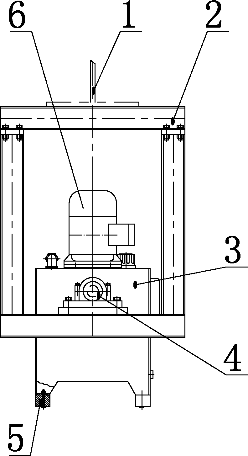
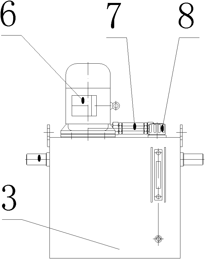
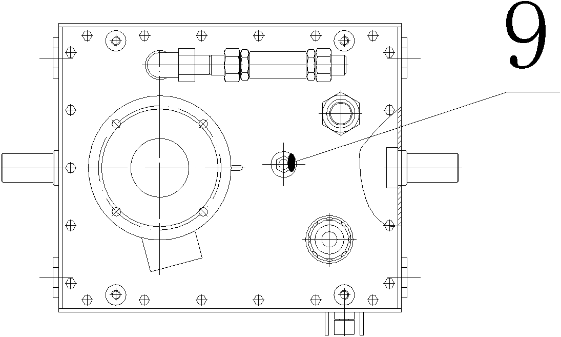
[0026] The self-adaptive hydraulic power device for the opening bridge is installed in the box girder of the opening bridge. The hydraulic power device includes a hydraulic mechanism 3, a rotating bracket 2 and a counterweight 5, and the rotating bracket is welded and fixed on the inner horizontal beam 1 of the opening bridge box girder. , The hydraulic power mechanism has a rotating shaft, and the rotating shaft has a self-aligning ball bearing with a seat 4 to connect the rotating bracket 2, and the bottom of the hydraulic power mechanism 3 is equipped with a counterweight 5.

[0027] The hydraulic power mechanism has a fuel tank, an oil pump motor unit 6, a liquid level controller 9, an air filter 8 and a one-way valve 7. The fuel tank is a closed box with double rotating shafts extending out. The double rotating shafts are the rotation centers of the fuel tank and the bridge. The oil pump The motor unit 6 is installed upside down on the top plate of the oil tank, the oil pu...


PUM


Abstract

The invention relates to a self-adapting type hydraulic power device for a movable bridge, which belongs to the technical field of hydraulic drive. The self-adapting type hydraulic power device is characterized by being installed in a box beam of the movable bridge and comprising a hydraulic mechanism, a rotating bracket and a weight balance block, wherein the rotating bracket is fixed to the box beam of a movable bridge beam; the hydraulic power mechanism is provided with a rotating shaft; the rotating shaft is connected with the rotating bracket by a bearing; and the bottom of the hydraulic power mechanism is provided with the weight balance block. The invention has the advantages of compact structure, convenience of assembly, high integrated degree, flexible start and shutdown of an oil pump, no overflow of hydraulic oil, high working efficiency, reliable performance, safe operation, and the like.

Description

technical field [0001] The invention belongs to the technical field of hydraulic transmission, in particular to an adaptive hydraulic power device for opening a bridge. Background technique [0002] At present, the existing hydraulic power devices are generally of a fixed structure, either fixed on the cement foundation, or integrated and fixed on the mechanical equipment, and are relatively fixed to the equipment body. [0003] The open bridge is a two-way vertically rotating open bridge. The driving mode of the bridge is driven by a hydraulic motor. The hydraulic motor is installed on the bridge. Due to the long hydraulic pipeline, the resistance loss along the pipeline is very large, which has exceeded the hydraulic motor shell. The pressure range that the body leakage can withstand. The casing of the hydraulic motor leaks oil, which must be transferred through the hydraulic oil tank to meet the operating conditions of the hydraulic motor. The hydraulic power unit has t...

Claims


Application Information

Patent Timeline
IPC IPC(8): E01D15/06
Inventor 雷江河董津宁王福山周然
Owner TIANJIN ENG MACHINERY INST
Learn More