Flat-pipe heat exchanger structure and assembling table thereof

A technology of heat exchangers and assembly tables, which is applied in the direction of tubular components, refrigeration components, heat exchange equipment, etc., can solve the problems of increased product cost, small contact area, and increased cold resistance, so as to reduce the use of welding processes and increase Contact area, effect of enhancing heat dissipation performance

Inactive Publication Date: 2011-05-18
LG ELECTRONICS (TIANJIN) APPLIANCES CO LTD
View PDF7 Cites 5 Cited by
  • Summary
  • Abstract
  • Description
  • Claims
  • Application Information

AI Technical Summary

Problems solved by technology

[0005] However, when the heat transfer requirement is large, the thickness of the tube-fin heat exchanger is limited, and the size of the windward side of the tube-fin heat exchanger is required to be large, resulting in a longer serpentine coil, longer refrigerant circulation channels, and refrigerant flow in the coil. The flow heat exchange in the tube, the length ratio of the formed gas phase area, gas-liquid two-phase area, and liquid phase area is unreasonable. Due to the long process, the liquid phase formed after the refrigerant passes through the gas phase area and the gas-liquid two-phase area is heat exchan

Method used


Image

  • Flat-pipe heat exchanger structure and assembling table thereof
  • Flat-pipe heat exchanger structure and assembling table thereof
  • Flat-pipe heat exchanger structure and assembling table thereof

Examples


Example Embodiment

[0027] The structure of the heat exchanger of the present invention will be further described below with reference to the accompanying drawings.

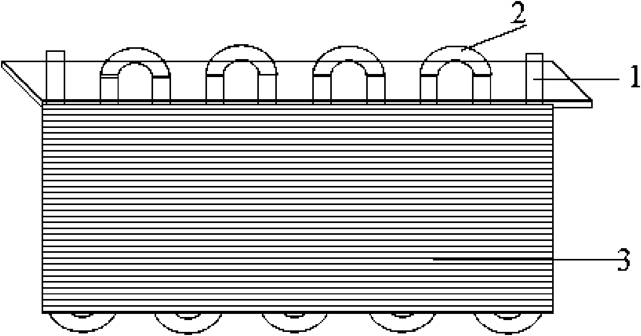
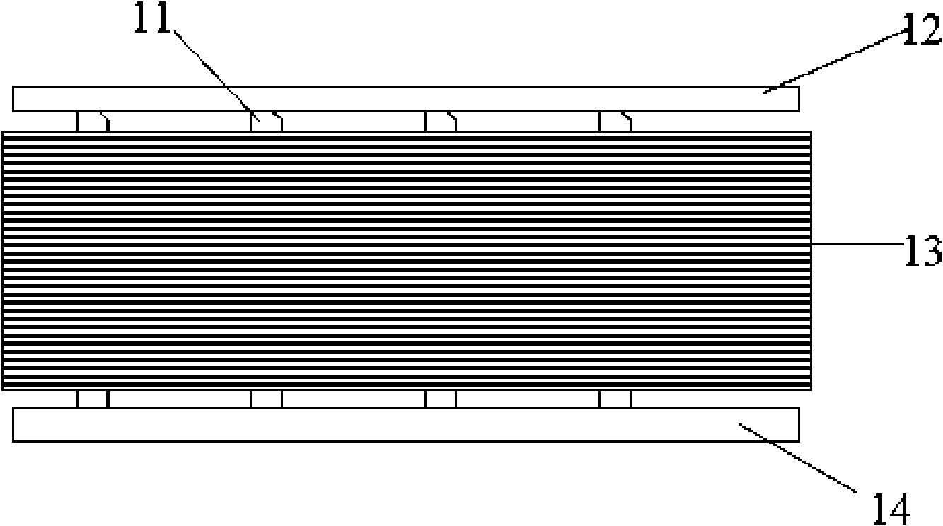
[0028] As shown in Figure 24, the heat exchanger structure of the present invention includes an inlet header 12, an outlet header 14, fins 13 that are tightly stacked between the inlet header 12 and the outlet header 14, and through the fins 13 will A flat pipe 11 in which the inlet header 12 and the outlet header 14 communicate.

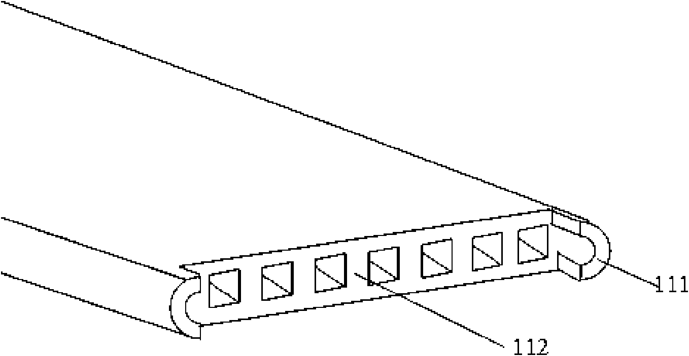
[0029] like image 3 As shown, the flat tube 11 of the present invention is a microchannel flat tube, generally an aluminum flat tube, and a plurality of partition plates 112 are arranged in its lumen, and the partition plates 112 extend along the pipeline direction of the flat tube 11 and The lumen is evenly divided into several microchannels. The cross-section of the flat tube 11 is a rounded rectangle, and the two arc-shaped side plates protrude forward in the direction of the pipe, that is, the two ...


PUM

PropertyMeasurementUnit
Lengthaaaaaaaaaa

Abstract

The invention discloses a flat-pipe heat exchanger structure which comprises an inlet header, an outlet header, fins and a flat pipe, wherein the fins are compactly stacked between the inlet header and the outlet header; the flat pipe communicates the inlet header with the outlet header by penetrating through the fins; the cross section of the flat pipe is a rounded rectangle; two side plates of the flat pipe project forward along the pipeline to form a leading end; the fins are provided with a pipeline groove; and the middle of the pipeline tank is provided with a rectangular opening of which the width is smaller than the thickness of the flat pipe. The invention also discloses an assembling table of the flat-pipe heat exchanger structure, which comprises a platform, wherein a through hole corresponding to the pipeline groove is formed on the edge of the platform. The fins in the heat exchanger structure are connected with the flat pipe in an interference mode, thereby maximally increasing the contact area of the fins and the flat pipe, benefiting heat abstraction, enhancing the heat abstraction performance of the heat exchanger, and ensuring the strength of the heat exchanger. By eliminating the welding procedure, the invention is easy to operate and saves more cost.

Description

technical field [0001] The invention relates to an air conditioner, in particular to a heat exchanger structure. Background technique [0002] When the room air conditioner is running in cooling mode, the indoor air flows through the evaporator to reduce the temperature. At the same time, because the temperature of the surface of the evaporator is generally significantly lower than the dew point temperature of the air, when the air flows through the surface of the evaporator, part of the moisture in the air will be precipitated, thereby forming condensed water on the surface of the evaporator. Condensed water on the surface of the evaporator should be drained in time. If the condensed water accumulates on the surface of the evaporator, it will block the air passage, increase the flow resistance of the air, and reduce the efficiency of the evaporator: water droplets may also be blown into the room, resulting in unqualified quality of the air conditioner. [0003] Finned tub...

Claims


Application Information

Patent Timeline
IPC IPC(8): F25B39/04F28F1/30
Inventor 崔静郭天东
Owner LG ELECTRONICS (TIANJIN) APPLIANCES CO LTD
Why Eureka
Try Eureka