
Method for welding doubly clad optical fiber and photonic crystal fiber

A technology of photonic crystal fiber and double-clad fiber, which is applied in the coupling of optical waveguide, light guide, optics, etc., can solve the problems of high loss, high splicing loss value, mismatched outer diameter, etc., and achieve high-quality, low-loss splicing , low-cost effect

Inactive Publication Date: 2011-05-18
NAT UNIV OF DEFENSE TECH
View PDF4 Cites 17 Cited by
  • Summary
  • Abstract
  • Description
  • Claims
  • Application Information

AI Technical Summary

Problems solved by technology

In the fusion splicing process of double-clad fiber and photonic crystal fiber, the main difficulties are: 1) the collapse of the air hole in the photonic crystal fiber leads to the destruction of its conduction mechanism and the introduction of high loss; 2) the mismatch of the mode field diameters of the two fibers The high loss introduced; 3) The outer diameter of the two optical fibers does not match, resulting in insufficient fusion strength or no fusion at all
These technical problems need to be overcome at the same time to achieve better results. For example, for two types of optical fibers with mismatched mode field diameters, even if the air hole of the photonic crystal fiber does not collapse, high losses can still be introduced due to the mismatched mode field diameters.
[0004] For the fusion splicing of two types of optical fibers with mismatched mode field diameters, the research team of the University of Bath in the UK proposed to connect the photonic crystal fiber and ordinary optical fiber when making the preform, and realize the mismatching mode field diameter when drawing the photonic crystal fiber. The connection between the photonic crystal fiber and ordinary optical fiber (see [S.G.Leon-Saval, T.A.Birks, N Y.Joly, A.K.George, W.J.Wadsworth, G.Kakarantzas, and P.S.J.Russell, "Splice-free interfacing of photonic crystalfibers", Opt .Lett., 30(13): 1629-1631(2005)]), but this method is quite complicated, and it needs drawing tower equipment to realize, so this method is not very practical
It is also proposed to introduce transition fiber to reduce the splice loss caused by the mismatch of mode field diameter. Such splice loss is lower than that of direct splice loss, but its splice loss value is still relatively high, and there is room for further improvement.
[0005] In addition, because the fusion of double-clad fiber and photonic crystal fiber is not only the mismatch of the mode field, but also the problem of the mismatch of the outer diameter, the mismatch of the outer diameter may cause the ordinary fusion splicer to fail to achieve the fusion operation or the fusion strength is too low
Therefore, how to reduce the fusion splicing loss between the double-clad fiber and the photonic crystal fiber whose outer diameter and mode field diameter do not match is a technical problem that is of great concern to those skilled in the art, but there is no published related report so far.

Method used


Image

  • Method for welding doubly clad optical fiber and photonic crystal fiber
  • Method for welding doubly clad optical fiber and photonic crystal fiber
  • Method for welding doubly clad optical fiber and photonic crystal fiber

Examples


Embodiment

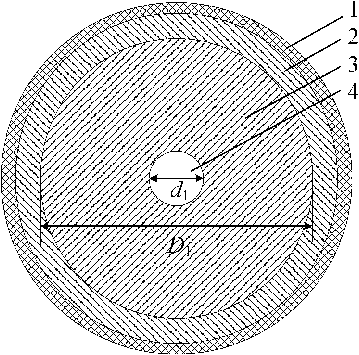
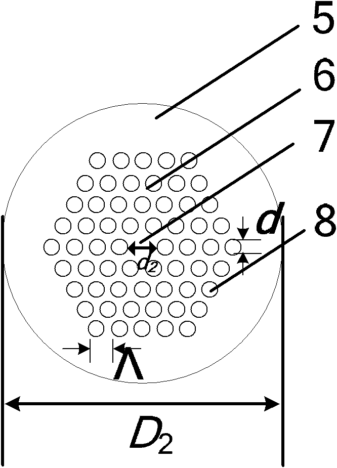
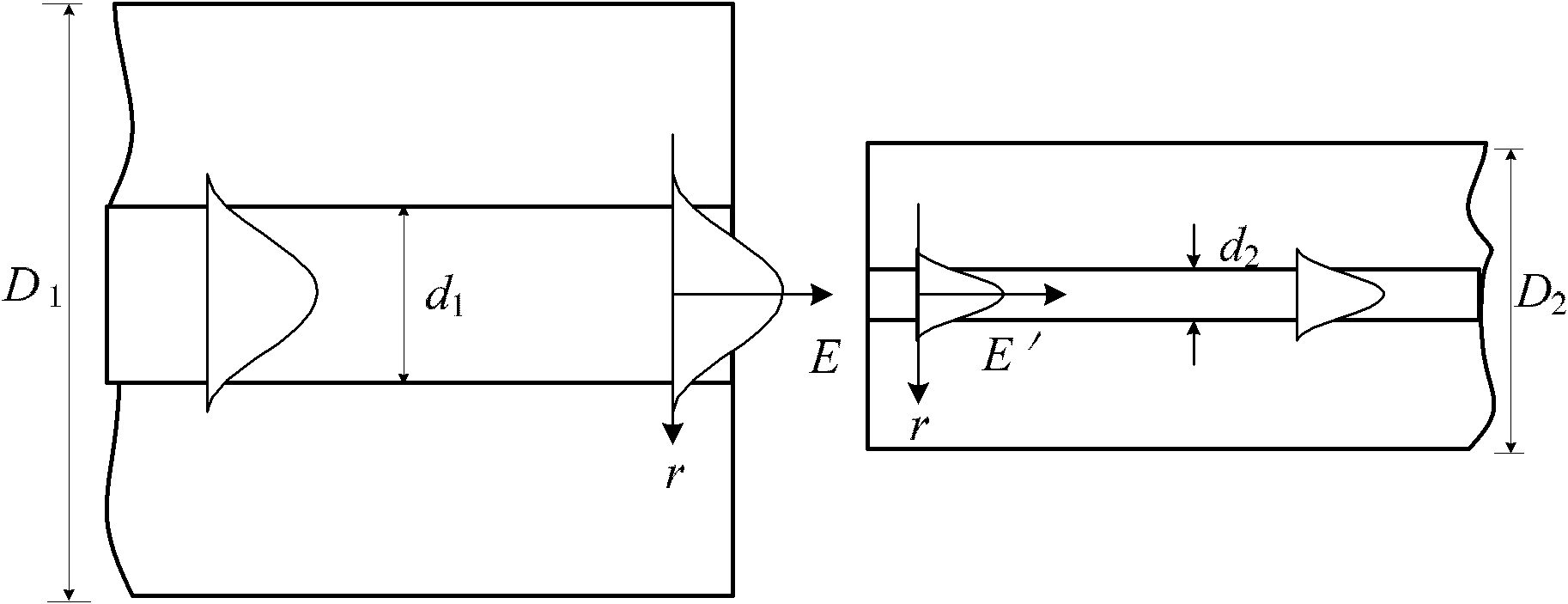
[0030] a kind of like figure 1 The shown double-clad optical fiber is composed of a protective layer 1 , an outer cladding 2 , an inner cladding 3 and a core 4 in sequence from outside to inside. The laser is transmitted in the fiber core 4, and the inner cladding 3 covered by the fiber core 4 is made of silica whose refractive index is smaller than that of the fiber core 4. The inner cladding 3 is the transmission channel of the pumping light, and its diameter is D 1 ; The outer cladding layer 2 covered by the inner cladding layer 3 is composed of a polymer with a smaller refractive index. The mode field diameter of double-clad fiber is generally all larger, and outer diameter is also bigger than common fiber and photonic crystal fiber, for example the double-clad fiber (Nufern company production, LMA-GDF-30 / 250 model) that present embodiment uses The outer diameter D 1 (that is, the diameter of the inner cladding 3) is 250 μm, the core diameter is 30 μm, and the mode fiel...


PUM

PropertyMeasurementUnit
Lengthaaaaaaaaaa

Abstract

The invention particularly discloses a method for welding a doubly clad optical fiber and a photonic crystal fiber. The method comprises the following steps of: reducing an outer diameter of the doubly clad optical fiber by a fused biconical taper method to ensure that the outer diameter of the doubly clad optical fiber is the same as that of the photonic crystal fiber; heating and collapsing air vent holes around the fiber core of the photonic crystal fiber to ensure that the module field diameter of the photonic crystal fiber is matched with that of the doubly clad optical fiber and keeping the outer diameter of the photonic crystal fiber basically unchanged; and welding the treated doubly clad optical fiber and the treated photonic crystal fiber by the conventional welding process. The method for welding the doubly clad optical fiber and the photonic crystal fiber has the advantages of low cost, high efficiency, high quality and simpleness and convenience.

Description

technical field [0001] The invention relates to an optical fiber fusion splicing method, in particular to a photonic crystal optical fiber fusion splicing method. Background technique [0002] Photonic crystal fiber, also known as microstructure fiber or holey fiber, has attracted much attention in recent years due to its novel optical properties. This type of fiber has broad application prospects in the fields of communication transmission, new optoelectronic devices, measurement and sensing, etc. Moreover, photonic crystal fibers have unique advantages in the field of nonlinear effects. By coupling pulsed light into photonic crystal fibers, it has become a research hotspot to study nonlinear effects and supercontinuum generation. [0003] In the field of fiber lasers, since most of the existing fiber lasers use the cladding pumping technology of double-clad fibers, the laser light of general fiber lasers is output from double-clad fibers. The double-clad fiber has the ch...

Claims


Application Information

Patent Timeline
IPC IPC(8): G02B6/255G02B6/245
Inventor 陈子伦侯静奚小明孙桂林陈胜平王泽锋司磊许晓军
Owner NAT UNIV OF DEFENSE TECH
Features
  • Generate Ideas
  • Intellectual Property
  • Life Sciences
  • Materials
  • Tech Scout
  • Unparalleled Data Quality
  • Higher Quality Content
  • 60% Fewer Hallucinations
Learn More