Passive temperature compensation mechanism for optical instrument

A temperature compensation, optical instrument technology, applied in optics, instruments, optical components, etc., can solve problems such as the performance of optical instruments cannot be guaranteed, the surface accuracy of optical parts is reduced, and the imaging quality of optical systems is affected, and controllable design variables can be achieved. Multiple, simple structure, the effect of eliminating adverse effects

Inactive Publication Date: 2011-05-18
CHANGCHUN INST OF OPTICS FINE MECHANICS & PHYSICS CHINESE ACAD OF SCI
View PDF3 Cites 10 Cited by
  • Summary
  • Abstract
  • Description
  • Claims
  • Application Information

AI Technical Summary

Problems solved by technology

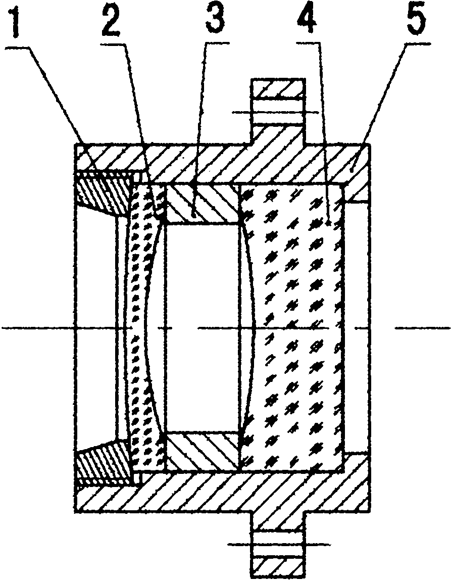
This structure is a relatively common fixed structure for optical components in optical instruments. The biggest disadvantage of this design is that it does not consider temperature compensation.
Since the thermal expansion coefficient of the lens base is generally greater than that of the optical element, when the temperature rises, the expansion of the lens base 5 is larger than that of the pressure ring 1, the first lens 2, the spacer 3, and the second lens 4 at the same length. The combined expansion is large, which will produce an axial gap, which cannot be controlled. When the temperature range is large, this axial gap will cause the preload applied by the pressure ring 1 to the first lens 2 to disappear. If the optical instrument is in a...

Method used


Image

  • Passive temperature compensation mechanism for optical instrument
  • Passive temperature compensation mechanism for optical instrument
  • Passive temperature compensation mechanism for optical instrument

Examples


Embodiment Construction

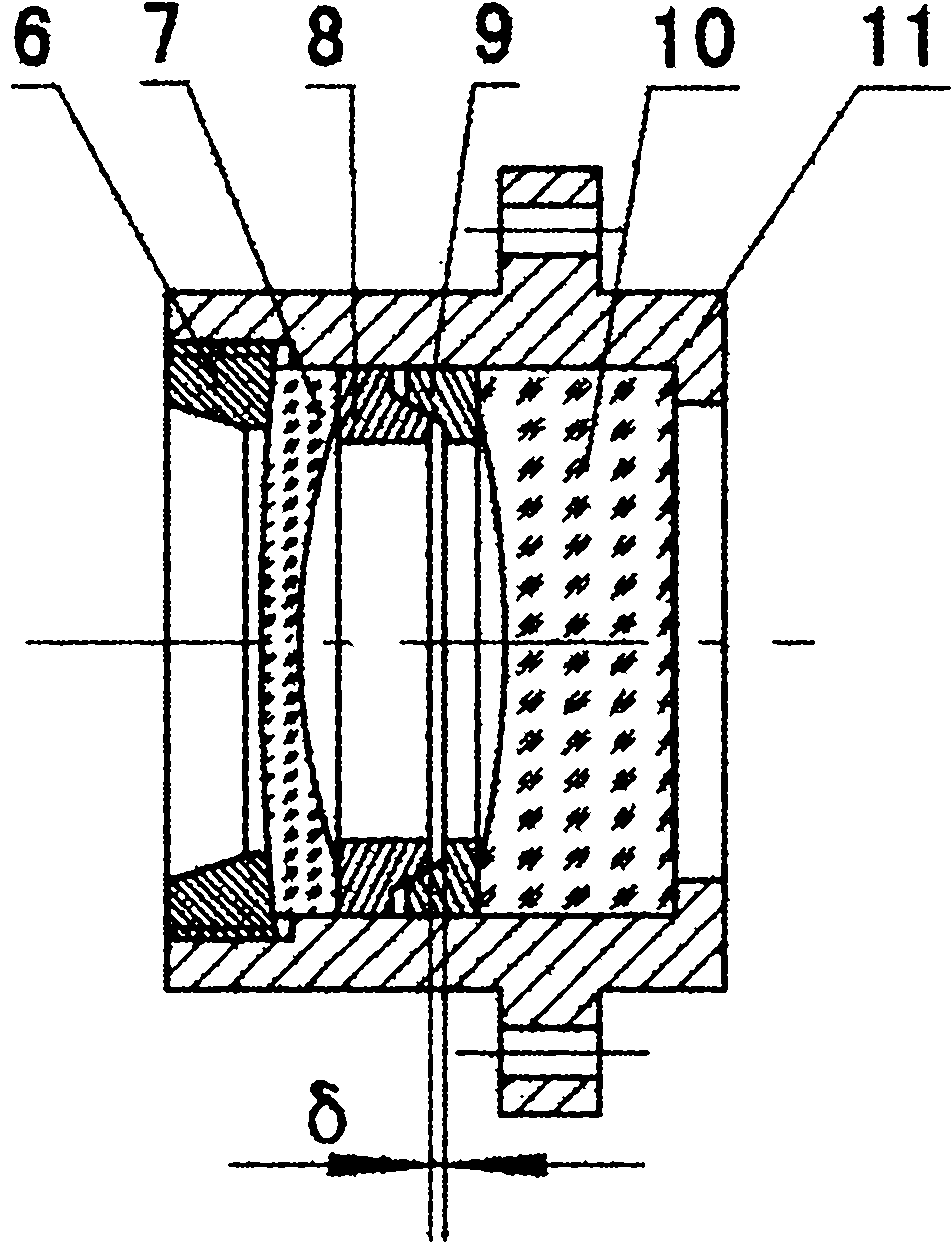
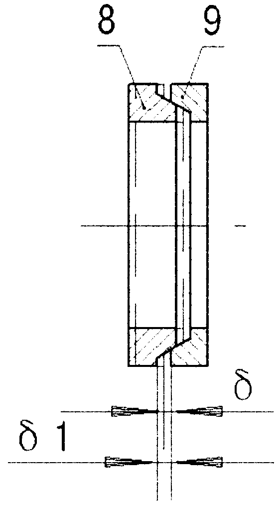
[0021] The present invention is figure 2 The shown structure is implemented, including the pressure ring 6, the first lens 7, the first spacer 8, the second spacer 9, the second lens 10, and the lens holder 11, where L, L 3 , L 4 , L 5 , C, C 3 , C 4 , C 5 It is fixed for a specific optical instrument, and α, C 1 , C 2 , L 1 , L 2 , D are design variables, and the specific implementation steps are as follows:

[0022] 1) Predetermine a wedge angle α between the spacers (30°1 , L 2 Contact the pitch diameter D with the two spacers;

[0023] 2) Select the material of the first spacer 8 and the second spacer 9, and C 1 >C 2 ;

[0024] 3) Calculate the axial gap β due to the difference in thermal expansion coefficient between the lens holder and the optical element when the temperature changes ΔT. The calculation formula is:

[0025] 4) Set Δδ equal to β, the wedge angle α can be calculated from formula (1);

[0026] 5) If the wedge angle α is slightly larger tha...


PUM


Abstract

The invention provides a passive temperature compensation mechanism for an optical instrument, relating to a mechanism in the technical field of precise optical mechanical system design. The passive temperature compensation mechanism for an optical instrument in the invention comprises a clamping ring, a first lens, a first space ring, a second space ring, a second lens and a lens seat. The optical axis in the lens seat is sequentially provided with the second lens, the second space ring, the first space ring, the first lens and the clamping ring from right to left; the right side of the second space ring is contacted with the left side of the second lens, a convex ring at the right side of the first space ring is put in a concave ring at the left side of the second space ring, the convex ring surface of the convex ring is contacted with the concave ring surface of the concave ring, the right side of the first lens is contacted with the left side of the first space ring, the first lens is clamped by the right surface of the clamping ring, and the edge of the clamping ring and the inner diameter of the lens seat are in thread contact to form a differential unit structure. The passive temperature compensation mechanism is simple in structure and is easy to realize, and good using effect is obtained when the mechanism is applied to an optical instrument used for aerial reconnaissance.

Description

technical field [0001] The invention belongs to a passive temperature compensation mechanism involved in the technical field of precision optical instrument design, in particular to a passive temperature compensation mechanism for an optical instrument used in aerial reconnaissance. Background technique [0002] The opto-mechanical system design of an optical instrument is a process that closely integrates various disciplines and technologies. The primary task of opto-mechanical engineers is to fix all the optical components in the optical system in their proper positions, and keep them at the required temperature and pressure. , vibration and other environmental conditions to maintain a certain position accuracy and surface accuracy, so that the optical system can work normally. [0003] For optical instruments used in aerial reconnaissance, the working temperature conditions are very harsh, and the imaging quality of the optical system will be degraded when the temperature...

Claims


Application Information

Patent Timeline
IPC IPC(8): G02B7/00
Inventor 王平戴明
Owner CHANGCHUN INST OF OPTICS FINE MECHANICS & PHYSICS CHINESE ACAD OF SCI
Why Eureka
Try Eureka