
Field bus interface for position detection element of numerical control machine

A field bus interface and detection element technology, applied in the field of numerical control, can solve the problems of large delay in transmission rate, limit increase in communication rate, decrease in communication rate, etc., and achieve the effects of high-speed communication, easy maintenance and low cost

Inactive Publication Date: 2011-05-18
HUAZHONG UNIV OF SCI & TECH +1
View PDF2 Cites 6 Cited by
  • Summary
  • Abstract
  • Description
  • Claims
  • Application Information

AI Technical Summary

Problems solved by technology

[0004] Therefore, increasing the communication rate of the serial bus is one of the ways to reduce the signal delay, but because the current serial bus signal adopts the level transmission method, the improvement of the communication rate is limited, usually only a few megabits, with the With the growth of transmission cables, the communication rate is gradually reduced
A lower transmission rate results in a greater delay, which affects the response speed and machining accuracy of the CNC machine tool
For example, the absolute code disc of a foreign brand adopts a communication rate of 2M to transmit a 31-bit code disc signal, plus the data frame header, frame tail and check digit of the bus, a total of 54 bits of data need to be transmitted. Produce a delay of at least 27 microseconds

Method used


Image

  • Field bus interface for position detection element of numerical control machine
  • Field bus interface for position detection element of numerical control machine
  • Field bus interface for position detection element of numerical control machine

Examples


Embodiment Construction

[0023] The present invention will be further described below in conjunction with the accompanying drawings and specific embodiments.

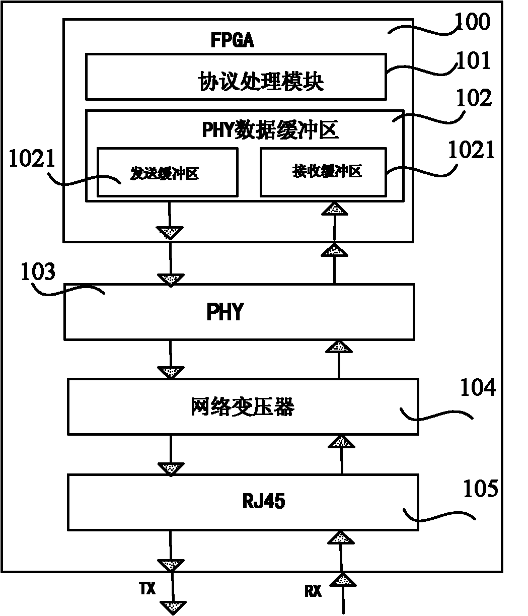
[0024] figure 1 It is the principle diagram of the field bus interface of the detection element, and the main content of the present invention is shown in the dotted line box. The position detection element is a relative or absolute rotary encoder or grating ruler, and the output signal is a parallel digital signal, which is connected to the field bus interface; the external control device (called the main control module) can be a servo drive device or a numerical control device , also connected to the same fieldbus interface. The field bus works in the master-slave mode, in which the external control device works in the master mode, and the bus detection element works in the slave mode.

[0025] The invention realizes the high-speed communication of the signal of the position detecting element by using the general Ethernet physical layer chi...


PUM


Abstract

The invention discloses a field bus interface for a bus type detection element of a numerical control machine, which is used for communication between a position detection element on the numerical control machine and an external control module of the numerical control machine. The interface comprises a field programmable gate array (FPGA), an Ethernet physical layer (PHY) chip, a network transformer and a twisted pair joint, wherein the field programmable gate array (FPGA) is used for the transmission buffer and reception buffer of data, and protocol processing; the Ethernet physical layer (PHY) chip communicates with the field programmable gate array (FPGA), and is used for transmitting and receiving the data and converting differential analogue signals transmitted in a network into digital signals for the processing of the field programmable gate array (FPGA); the network transformer is connected with the Ethernet physical layer (PHY) chip, and is used for isolating the signals; and the twisted pair joint is connected with the network transformer, and is used for transmitting and receiving the analogue signals. The field bus interface can increase the communication rate of a bus to 100M and reduce transmission delay to be within one microsecond, and meets the requirements of high-speed and high-accuracy machining of the conventional numerical control machine.

Description

technical field [0001] The invention belongs to numerical control technology, and in particular relates to a field bus interface of a position feedback element of a numerical control machine tool. Background technique [0002] In the CNC machine tool control system, the position detection element generally adopts an encoder or a grating ruler, and its signal interface is generally in the form of TTL level, 1VPP sine-cosine pulse train or serial encoding. If the signal is transmitted in the form of a pulse train, it is susceptible to electromagnetic interference in the industrial environment and is not suitable for high-frequency transmission in the industrial field. [0003] In order to improve the accuracy of position feedback, in the CNC machine tool control system, the interface between the position feedback components and the control device has appeared a digital communication method using serial bus transmission. At present, most of the position feedback devices and in...

Claims


Application Information

Patent Timeline
Patent Type & Authority Applications(China)
IPC IPC(8): G05B19/414
Inventor 宋宝唐小琦夏亮马泽龙周向东任雁胜周彬唐玉枝
Owner HUAZHONG UNIV OF SCI & TECH
Learn More