Series capacitors-running single phase permanent magnet synchronous generator
A synchronous generator and single-phase permanent magnet technology, which is applied to synchronous motors with stationary armatures and rotating magnets, synchronous machine parts, electrical components, etc., can solve the problem of single-phase permanent magnet generator synchronous generators. Realize and affect the normal operation of the generator, etc., to achieve the effect of reducing vibration and noise, suppressing vibration and noise, and increasing output power
- Summary
- Abstract
- Description
- Claims
- Application Information
AI Technical Summary
Problems solved by technology
Method used
Image
Examples
Embodiment 1
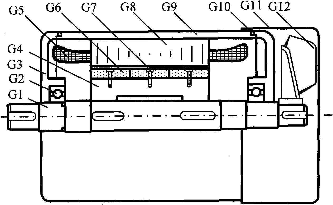
[0038] Depend on figure 1 It can be seen that the rotor of the single-phase permanent magnet synchronous generator operated by series capacitors of the present invention adopts a surface magnetic steel structure, and the permanent magnetic steel G6 is fixed on the rotor core G4 with stainless steel screws G7, and the rotor core G4 is processed from No. 20 steel ; The rotor core G4 is installed on the rotating shaft G1, and the rotating shaft G1 is supported on the end cover G3 through two bearings G2 at both ends, and the end cover G3 is fixed on both ends of the casing G9 and sealed by the O-shaped sealing gasket G10; the fan G12 is fixed On the end of the non-mechanical input end of the rotating shaft G1, the generator is air-cooled, and the fan cover G11 is set on the non-mechanical input end of the casing G9 as a safety shield for the fan G12.
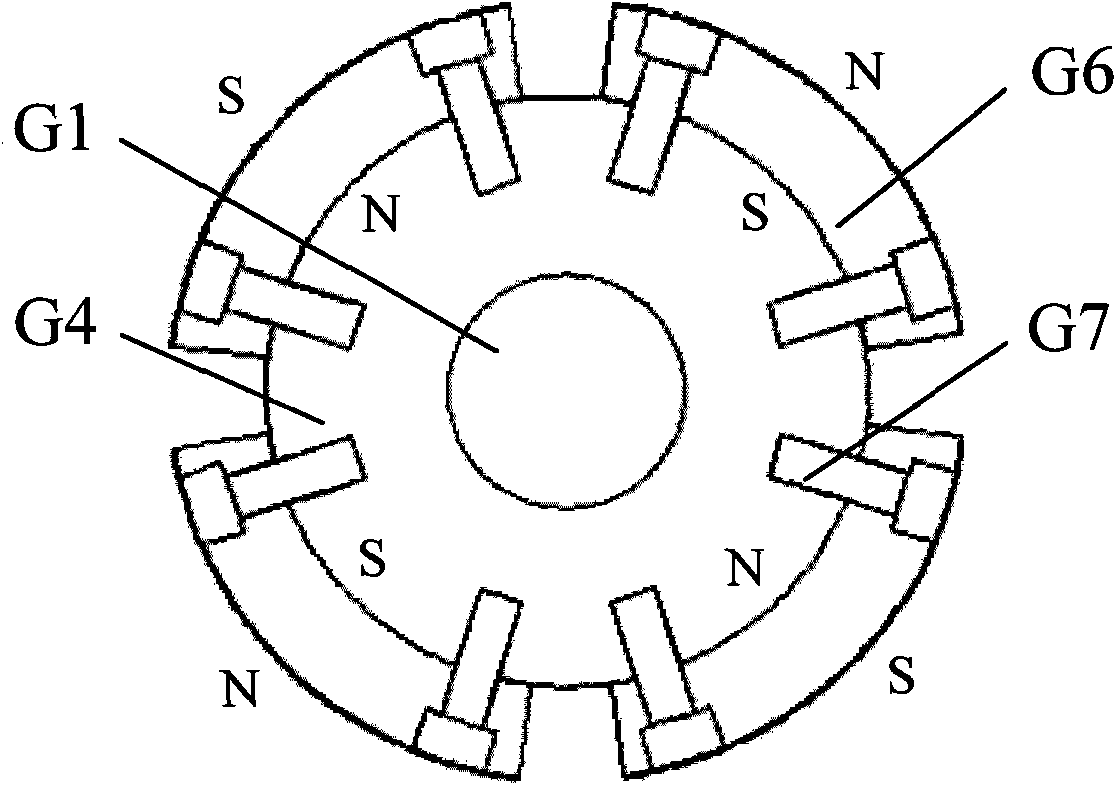
[0039] Such as figure 2 As shown, the number of poles of the generator in this embodiment is 4 poles, N and S magnetic poles ar...
Embodiment 2
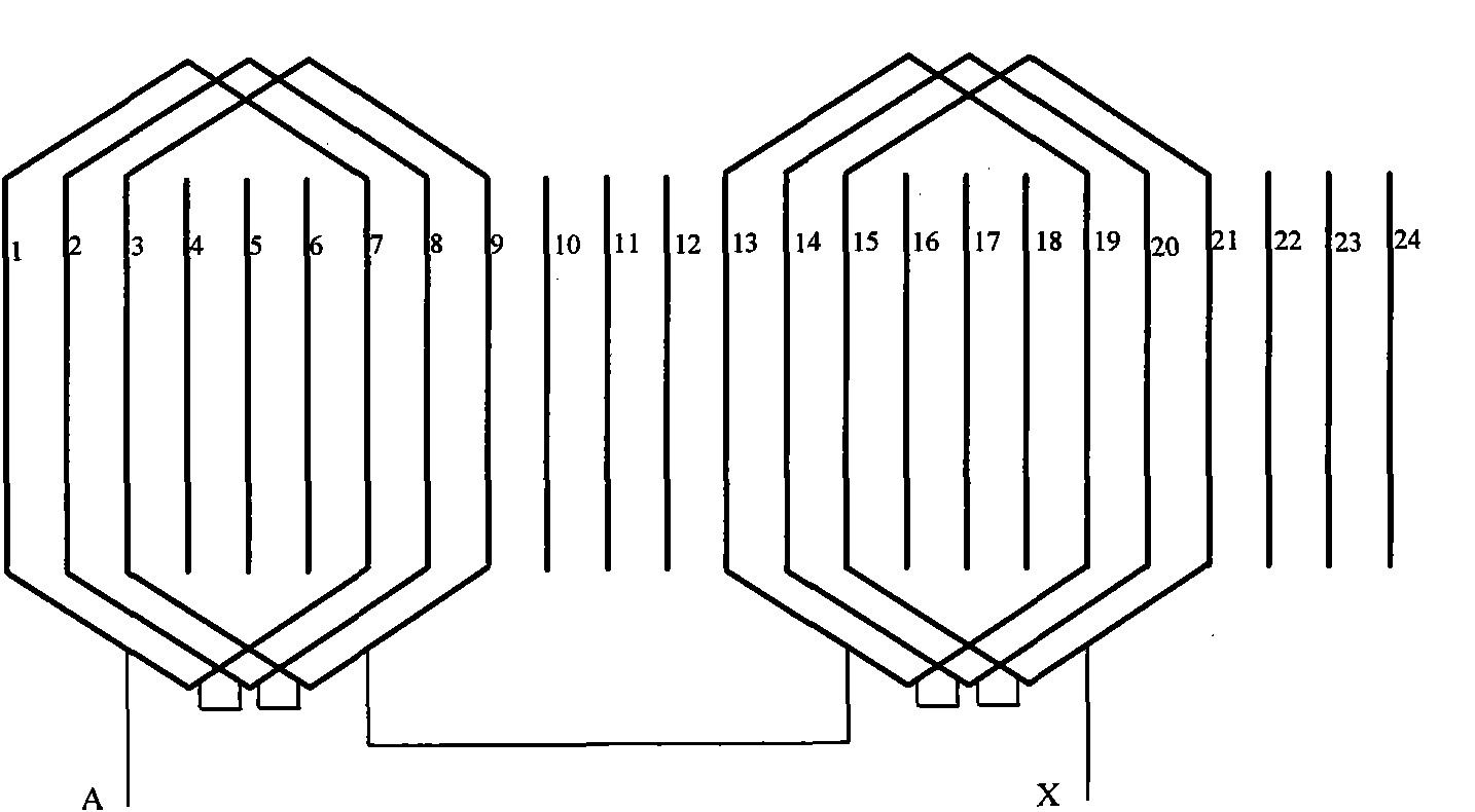
[0045] The overall structure of the generator in this embodiment is the same as that in Embodiment 1, but the A and B two-phase armature windings with 4 poles and 24 slots adopt double-layer short-distance distributed windings to further weaken the influence of harmonic magnetic field on induced electromotive force. Such as figure 1 As shown, the A and B two-phase armature windings G5 with a mutual difference of 90 degrees in electrical angle are placed in the stator core G8. Among them, the schematic diagram of the distribution of the phase A double-layer short-distance distributed winding is as follows: Figure 8 As shown, the number of slots per pole and phase is 3, and the number of winding pitches is 5, that is, the first coil is placed in the No. 1 slot of the stator core G8, the tail side is placed in the No. 6 slot, and so on. The first side (upper side) of each coil of the A-phase winding is placed in the stator slots with slot numbers (1, 2, 3, 7, 8, 9, 13, 14, 15, ...
Embodiment 3
[0048] The overall structure of the generator in this embodiment is the same as that in Embodiment 1, but the two-phase armature winding with 4 poles and 36 slots adopts a fractional slot winding to further weaken the influence of the cogging harmonic field on the induced electromotive force in the armature winding. Such as figure 1 As shown, the A and B two-phase armature windings G5 with a mutual difference of 90 degrees in electrical angle are placed in the stator core G8. The schematic diagram of the distribution of phase A fractional slot windings is as follows: Figure 9 Shown, the number of slots per pole per phase is , For example, there are 4 consecutive slots under a pole belonging to the A-phase winding, and there are 5 slots under the adjacent pole belonging to the A-phase winding. The number of winding pitches is 7, that is, the first side of the first coil is placed in the No. 1 slot of the stator core G8, the tail side is placed in the No. 8 slot, and so on. ...
PUM
 Abstract
Description
Claims
Application Information
 - R&D
- Intellectual Property
- Life Sciences
- Materials
- Tech Scout
- Unparalleled Data Quality
- Higher Quality Content
- 60% Fewer Hallucinations
Browse by: Latest US Patents, China's latest patents, Technical Efficacy Thesaurus, Application Domain, Technology Topic, Popular Technical Reports.
© 2025 PatSnap. All rights reserved.Legal|Privacy policy|Modern Slavery Act Transparency Statement|Sitemap|About US| Contact US: help@patsnap.com


