One-cycle controlled constant-power electronic ballast for high intensity discharge (HID) lamp and control method of electronic ballast

A single-cycle control, electronic ballast technology, applied in the use of electric light sources, electrical components, gas discharge lamps, etc., can solve problems such as affecting control accuracy, cumbersome calculation of constant power adjustment, and system oscillations

Active Publication Date: 2011-05-18
山东智慧照明科技有限公司
View PDF3 Cites 10 Cited by
  • Summary
  • Abstract
  • Description
  • Claims
  • Application Information

AI Technical Summary

Problems solved by technology

[0007] 1) The high-frequency potential of the electrode of the HID lamp is the same as that of an output terminal of the inverter bridge. As the two upper bridge arms of the inverter bridge alternately work in the high-frequency PWM modulation mode, high-amplitude voltages will appear on the electrodes of the HID lamp at intervals. High-frequency PWM pulse voltage causes severe electromagnetic interference, and electromagnetic compatibility is difficult to meet the requirements of relevant specifications
[0008] 2) The calculation of the constant power adjustment of the system is cumbersome, and it is easily affected by the discreteness of the system parameters
[0012] By comparing the calculated value of the lamp power (V lamp ·I lamp ) and the set value to adjust the reference value of the peak current, so as to realize the adjustment of the output power and achieve the purpose of outputting constant power; any deviation of any variable in the above calculation formula will affect the control accuracy
[0013] 3) The system control method adopts PWM peak current control, which is easily affected by system noise, resulting in system oscillation and other problems

Method used


Image

  • One-cycle controlled constant-power electronic ballast for high intensity discharge (HID) lamp and control method of electronic ballast
  • One-cycle controlled constant-power electronic ballast for high intensity discharge (HID) lamp and control method of electronic ballast
  • One-cycle controlled constant-power electronic ballast for high intensity discharge (HID) lamp and control method of electronic ballast

Examples


Embodiment Construction

[0069] The present invention will be further described below in conjunction with the accompanying drawings and embodiments.

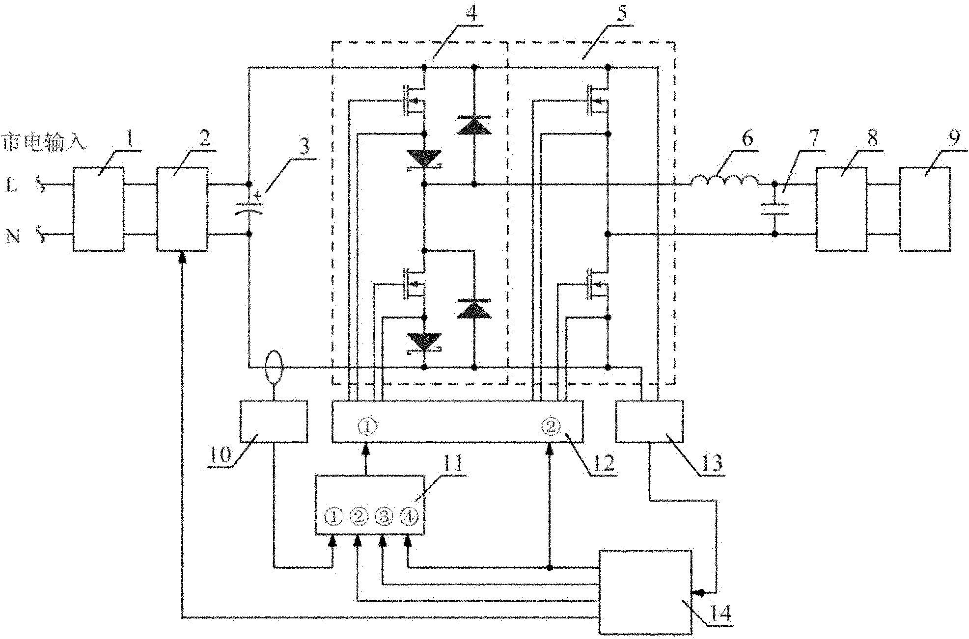
[0070] figure 1 It is a structural schematic diagram of the first embodiment of the single-cycle control constant power HID lamp electronic ballast.

[0071] Such as figure 1 As shown, a single-cycle control constant power HID lamp electronic ballast is characterized in that it includes 4 high-frequency inverter half-bridges and 5 low-frequency inverter half-bridges, the 4 high-frequency inverter half-bridges and 5 low-frequency inverter half-bridges The inverter half-bridges share the same DC bus; 3 energy storage capacitors are connected between the two poles of the DC bus, and are connected to the output terminals of the 2 high power factor rectifier units; the input terminals of the 2 high power factor rectifier units are connected to 1 electromagnetic compatibility filter unit Output terminal, 1. The input terminal of the electromagnetic compatib...


PUM


Abstract

The invention relates to a one-cycle controlled constant-power electronic ballast for a high intensity discharge (HID) lamp and a control method of the electronic ballast. The electronic ballast has the advantages of high overall efficiency, good electromagnetic compatibility, stable and reliable system, simple structure and the like, and is easy in implementation. The electronic ballast comprises an electromagnetic compatible filtering unit, a high power factor rectifying unit, an energy storage capacitor, a high frequency inverted half bridge, a low frequency inverted half bridge, a filter inductor, a filter capacitor and an ignition unit which are connected in sequence, wherein the input end of the electromagnetic compatible filtering unit is connected with commercial power; the outputend of the ignition unit is connected with the HID lamp; the high frequency inverted half bridge and the low frequency inverted half bridge are respectively connected with a drive unit; the drive unit is connected with a one-cycle controller and a main control unit; the one-cycle controller is connected with a current detection unit and the main control unit; the current detection unit is connected in the input loop of a direct current (DC) bus in series; the main control unit is connected with a voltage detection unit; and the voltage detection unit is connected with the DC bus.

Description

technical field [0001] The invention belongs to the technical field of electronic drive for high-intensity gas discharge lamps, in particular to an electronic ballast for single-cycle control constant power HID lamps and a control method thereof. Background technique [0002] HID (High intensity discharge) lamps, also known as high-intensity gas discharge lamps, have become widely used light sources in outdoor lighting because of their high luminous efficiency and good light color. Common HID lamps include high-pressure sodium lamps, high-pressure mercury lamps, ceramic HID lamps, and xenon lamps. The traditional driving method of HID lamps is the magnetic ballast method. The advantage of this driving method is that the lighting system is simple in structure, low in cost, and the ballast is reliable and durable; its disadvantages are that the driven light source has a power-frequency strobe, the system input power factor is low, and the output power is seriously affected by...

Claims


Application Information

Patent Timeline
Patent Type & Authority Applications(China)
IPC IPC(8): H05B41/288H05B41/36
CPCY02B20/202Y02B20/00
Inventor 田中林李建明
Owner 山东智慧照明科技有限公司
Why Eureka
Try Eureka