
Adaptive welding method for pipe-plate circumference welding and subsection parameter setting and arc welding equipment

A technology for setting parameters and arc welding equipment, which is applied in the direction of arc welding equipment, welding equipment, metal processing equipment, etc., can solve the problems of affecting welding quality, low welding pass rate, and low welding efficiency, so as to improve weld formation The effect of improving welding pass rate and improving welding efficiency

Active Publication Date: 2011-05-25
SHENZHEN RILAND IND
View PDF1 Cites 11 Cited by
  • Summary
  • Abstract
  • Description
  • Claims
  • Application Information

AI Technical Summary

Problems solved by technology

[0003] 1. If the only parameter is set at the time of overhead welding, the welding efficiency will be low, the forming effect will be poor and the welding qualification rate will be low;
[0004] 2. If the only parameter is set in the vertical welding, although the welding efficiency has been improved, the welding efficiency is still relatively low, the forming effect is not good and the welding pass rate is not high; and in the overhead welding, the molten pool ( molten iron) will flow down, so that the surface of the weld cannot meet the forming requirements, which will affect the quality of welding;
[0005] 3. If the only parameter is set for flat welding, the molten pool (molten iron) will flow downward during overhead welding and vertical welding, which will also make the weld surface unable to meet the forming requirements and affect the quality of welding

Method used


Image

  • Adaptive welding method for pipe-plate circumference welding and subsection parameter setting and arc welding equipment
  • Adaptive welding method for pipe-plate circumference welding and subsection parameter setting and arc welding equipment
  • Adaptive welding method for pipe-plate circumference welding and subsection parameter setting and arc welding equipment

Examples


Embodiment Construction

[0043] The present invention will be described in further detail below in conjunction with the accompanying drawings.

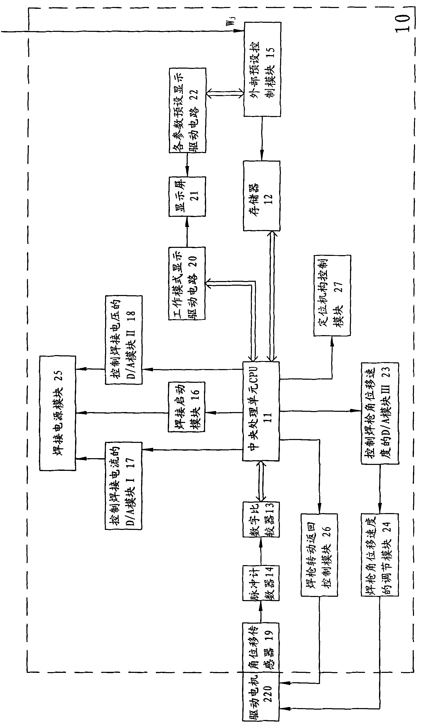
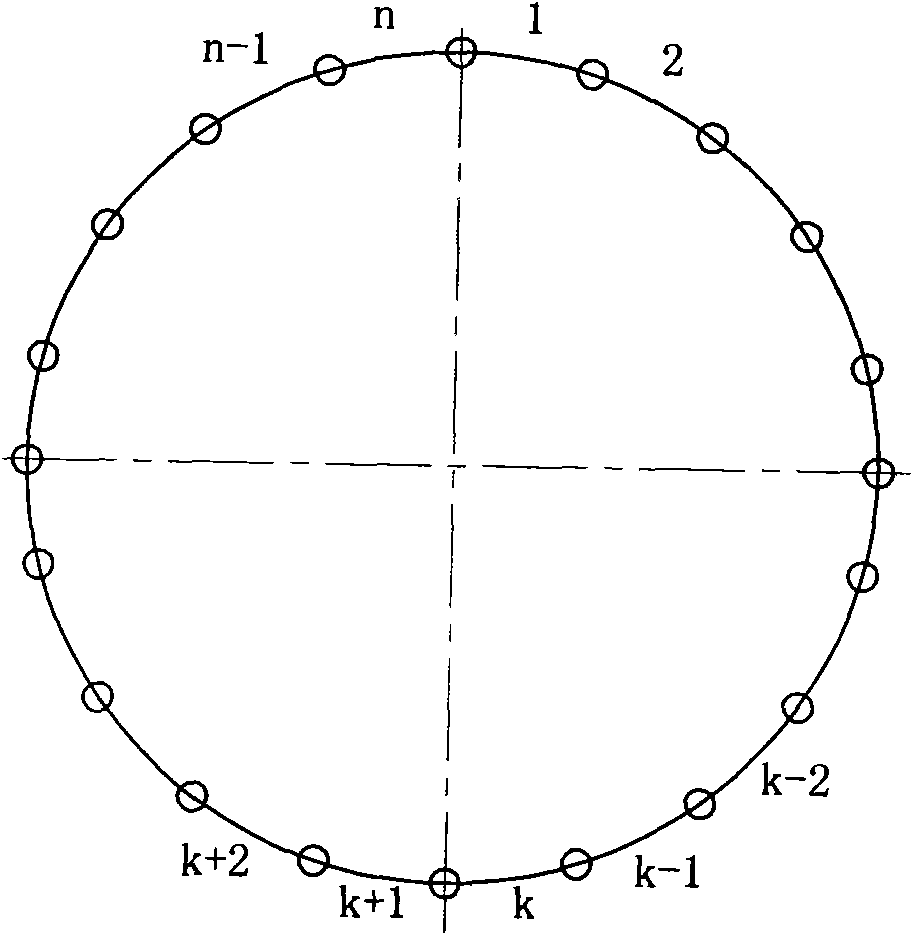
[0044] see figure 1 and figure 2 , the present invention relates to a kind of adaptive welding method for tube-plate circumferential welding, segmentally set parameters, comprising the following steps:

[0045] A. Divide the circumferential weld of the tube-plate to be welded into n arc segments, where n is an integer, and 20≥n≥2. There are different process requirements according to the different geometric positions of each arc segment, and each arc is preset. Section welding parameters W j ={I j , U j , β j}, j=1 to n, where I j , U j and beta j Respectively, the angular displacement of the welding torch rotation corresponding to the welding current, welding voltage and arc length of the arc section welding seam required by the welding process of the jth arc section on the circumferential weld seam;

[0046] B. Will implement the n sets of welding...


PUM


Abstract

The invention discloses an adaptive welding method for pipe-plate circumference welding and subsection parameter setting, which comprises the following steps of: dividing the circumferential seam of a welded workpiece pipe-plate into n arc sections, and presetting the welding parameter of each arc section; storing n groups of preset welding parameters in a memory; placing a welding gun at a welding start position; switching on a welding power supply, taking out the welding parameters from the memory under the control of a central processing unit to control welding current and voltage suppliedto the arc section by the welding power supply and control arc striking and arcing of the welding gun, and rotating the welding gun to complete the angular displacement of a given value; and after the welding gun completes welding of the arc section, taking the welding parameter of the next arc section to continuously implement welding till completing welding of all n arc sections. The adaptive welding method can save welding materials, improve the welding efficiency, improve the seam forming efficiency and improve the welding qualification rate and the like, is greatly convenient for most users, and is particularly suitable for welding thick-wall pipes and thick plates.

Description

【Technical field】 [0001] The present invention relates to gas flame welding, in particular to gas-shielded welding of circumferential seams, especially to an adaptive welding method for tube-plate circumferential welding with segmentally set parameters, and the present invention also relates to tube-plate circumferential welding The self-adaptive arc welding equipment that sets parameters in sections. 【Background technique】 [0002] The prior art automatic welding equipment includes an arc welding equipment for tube-to-plate circumferential welding, which is commonly used in the boiler industry. When welding the tube-plate circumference, the parameters such as current, voltage and welding speed required for each arc section of the circumference should be different, so as to ensure that the arc welding equipment is used for tube-plate circumference welding with high welding efficiency and good forming effect Good and high welding qualification rate; if the current and voltag...

Claims


Application Information

Patent Timeline
Patent Type & Authority Applications(China)
IPC IPC(8): B23K9/16
Inventor 邱光汪清华
Owner SHENZHEN RILAND IND
Learn More