Structural steel and forged steel stud butt joint welding method for hull

A welding method and a technology for structural steel, applied in welding equipment, welding/welding/cutting items, arc welding equipment, etc., can solve the problems of low weld strength and heavy welding workload, so as to reduce production costs and improve labor Efficiency, reducing the effect of welding deformation

Active Publication Date: 2016-01-13
WUCHANG SHIPBUILDING IND
View PDF9 Cites 4 Cited by
  • Summary
  • Abstract
  • Description
  • Claims
  • Application Information

AI Technical Summary

Problems solved by technology

[0003] The invention provides a vertical butt welding method between steel for hull structure and forged steel, which solves the problems of low weld strength and large welding workload existing in the vertical butt welding method between high-strength structural steel and forged steel. Special 902 steel and SA508-3 forged steel vertical butt welding to save welding materials, electric energy and man-hours, and easy to process, effectively reducing welding deformation

Method used


Image

  • Structural steel and forged steel stud butt joint welding method for hull
  • Structural steel and forged steel stud butt joint welding method for hull

Examples


Embodiment 1

[0021] Embodiment 1, comprises the following steps:

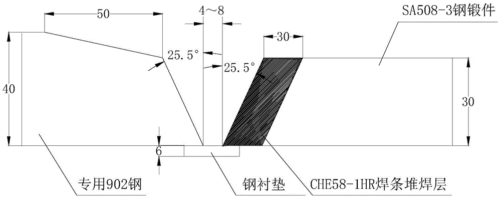
[0022] (1) Groove forming steps: such as figure 1 As shown, grooves are formed on the butt joints of special 902 steel with a thickness of 40mm and SA508-3 forged steel with a thickness of 30mm, without leaving roots, and the inclination angles of the grooves on both sides are symmetrical. The groove angle is 51°, and the part of the special 902 steel side thicker than the SA508-3 forged steel is beveled, and the bevel length is 50mm, so that the two sides of the butt joint groove are of the same height; Water stains, oil stains, rust, hanging slag and other sundries that affect the welding quality should be removed;

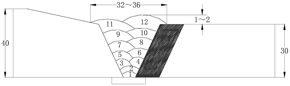
[0023] (2) One-side surfacing welding step: Preheat the SA508-3 forged steel groove area to 120°C, and then use manual arc welding and φ4mm CHE58-1HR electrode to perform surfacing welding on the SA508-3 forged steel groove. The shape of the layer is consistent with the groove, and the thickness is 30mm±2mm...

Embodiment 2

[0029] Embodiment 2, is exactly the same as the step of embodiment 1, and difference is only in the process parameter in each step:

[0030] In the groove forming step, the butt groove angle is 60°, and the bevel length is 45mm;

[0031] In the surfacing step on one side, preheat to 80°C;

[0032] Preheating step The gap between the butt groove and the groove is 4mm, the angle of the butt groove is 60°, and a Q345R steel liner with a thickness of 4mm is installed; the preheating temperature reaches 80°C and starts welding;

[0033] In the welding step, the temperature between passes during welding is controlled at 80°C.

[0034] In the single-side surfacing welding step and welding step of each of the above-mentioned embodiments, the electrodes involved need to be baked at 380-400°C for 1-2 hours before welding, and put them into the heat preservation bucket to be used at any time. After 4 hours, the unused The welding rod should be taken out and re-baked, and the number of ...


PUM


Abstract

The invention provides a structural steel and forged steel stud butt joint welding method for a hull and belongs to a welding method among high-strength steel materials. The method solves the problems that by means of an existing high-strength structural steel and forged steel stud butt joint welding method, the welding seam strength is low, and the welding workload is large. The method includes the steps of groove forming, unilateral bead welding, preheating and welding. By means of the structural steel and forged steel stud butt joint welding method, machining is easy, welding deformation is reduced effectively, special 902 steel and SA508-3 forged steel stud butt joint welding is achieved smoothly, weldability test and welding process evaluation are achieved, labor efficiency can be improved, welding materials and electric energy are saved, man hours are reduced, production cost is lowered, the building period of ships is reduced, and the blank in structural steel and high-strength forged steel stud butt joint welding for ships in China is filled.

Description

technical field [0001] The invention belongs to a welding method between high-strength steel materials, in particular to a vertical butt welding method of ship hull structural steel and forged steel. Background technique [0002] Welding technology is one of the key technologies of modern shipbuilding engineering, and the quality of ship welding in hull construction is an important indicator for evaluating shipbuilding quality. In the field of steel structure manufacturing involving special requirements and harsh working conditions (such as irradiation conditions), high-strength steel occupies an increasingly important position and has been widely used in ships, bridges, petrochemicals, high-rise building construction, and nuclear power plant construction. and other fields. Internationally, high-strength steel welding technology has developed rapidly in terms of welding material composition and process design, and its application fields are also expanding. The application ...

Claims


Application Information

Patent Timeline
Patent Type & Authority Applications(China)
IPC IPC(8): B23K9/02B23K9/04B23K9/235
CPCB23K9/02B23K9/042B23K9/235B23K2103/04
Inventor 王波
Owner WUCHANG SHIPBUILDING IND
Why Eureka
Try Eureka