
Electronic mutual inductor test system and test method

An electronic transformer and testing system technology, applied in instruments, measuring devices, measuring electrical variables, etc., can solve problems such as inability to test electronic transformers, and achieve rapid and reliable boosting process, small capacity, and guaranteed reliability. Effect

Active Publication Date: 2011-05-25
HEFEI POWER SUPPLY COMPANY OF STATE GRID ANHUI ELECTRIC POWER +1
View PDF3 Cites 39 Cited by
  • Summary
  • Abstract
  • Description
  • Claims
  • Application Information

AI Technical Summary

Problems solved by technology

However, traditional transformer testing methods and equipment cannot test electronic transformers, so there is an urgent need for a system that can test electronic transformers

Method used


Image

  • Electronic mutual inductor test system and test method
  • Electronic mutual inductor test system and test method
  • Electronic mutual inductor test system and test method

Examples


Embodiment Construction

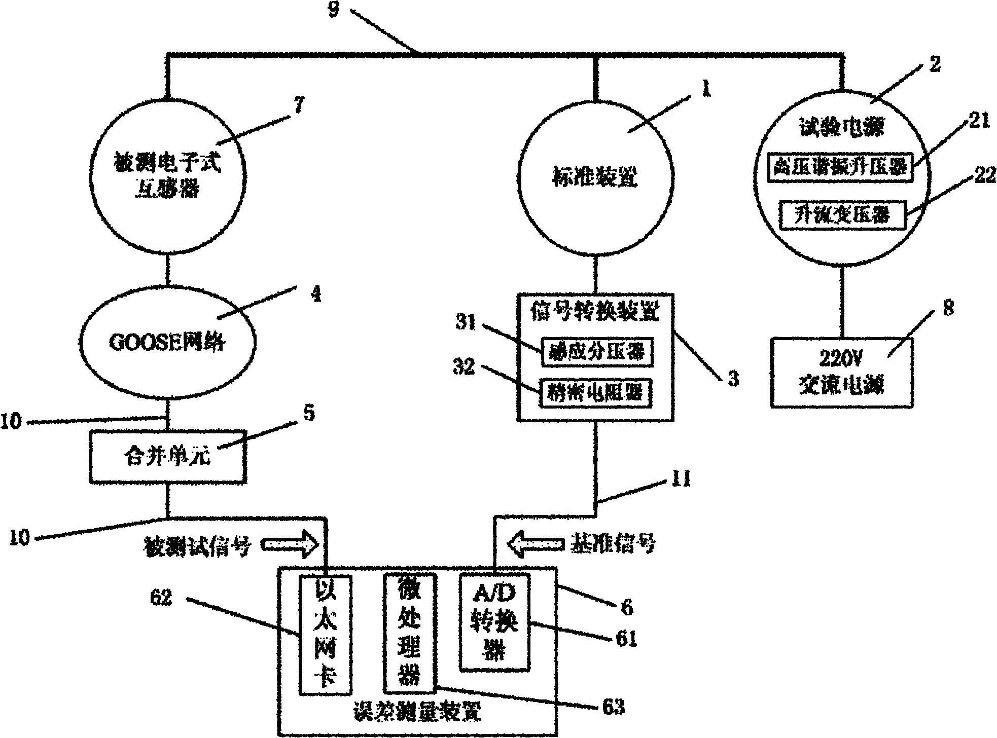
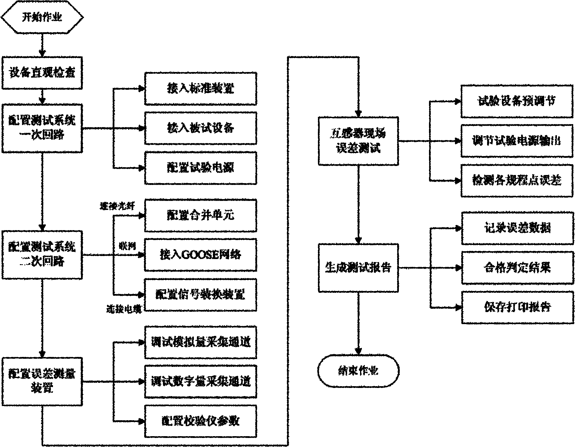
[0038] see figure 1, the electronic transformer testing system includes a standard device 1, a signal conversion device 3, an error measuring device 6, a test power supply 2, a merging unit 5 and a tested electronic transformer 7; the tested electronic transformer 7 and the standard device 1 The primary side is connected to the primary test lead 9; the test power supply 2 connected to the primary test lead 9 is connected to the AC power supply 8 and powered by the AC power supply 8; the standard device 1, the secondary side output of the standard device 1 The standard signal used as a test reference, the standard signal includes a standard voltage signal and a standard current signal; the standard signal is an analog signal; the signal conversion device 3 is connected to the secondary side of the standard device 1, and is used to receive the standard device 1 to generate and process the standard signal to convert the standard signal into an analog signal that can be collected ...


PUM


Abstract

The invention discloses an electronic mutual inductor test system and a test method. The electronic mutual inductor test system comprises a standard device, a signal conversion device, an error measuring device, a test power supply, a merging unit and a tested electronic mutual inductor, wherein the standard device is used for providing a standard signal serving as a test reference; the signal conversion device is used for receiving the standard signal and converting the standard signal into an analog signal which can be acquired by the error measuring device; the test power supply is used for outputting a primary voltage and a primary current for test use; the merging unit is used for receiving a digital signal output by the tested electronic mutual inductor and processing the digital signal; and the error measuring device is used for receiving the standard signal output by the signal conversion device and the digital signal output by the merging unit, and acquiring the ratio difference and the phase difference of the tested electronic mutual inductor. The electronic mutual inductor test system is particularly suitable for a field error test of the electronic mutual inductor, andhas the advantages of convenient test work, high reliability, small equipment volume, light weight, high test result accuracy and the like.

Description

technical field [0001] The invention relates to an electronic transformer testing system and a testing method, in particular to an electronic transformer testing system and a testing method for on-site error testing of the electronic transformer. Background technique [0002] Transformer is a device that converts voltage or current in proportion. Its main function is to convert high voltage or high current into standard low voltage or standard small current in proportion, so as to realize the standardization and miniaturization of measuring instruments, protection equipment and automatic control equipment. change. With the rapid development of optical fiber sensing technology and optical fiber communication technology, optoelectronic technology is more and more widely used in power systems, and electronic transformers have also emerged as the times require. Electronic transformer has many advantages such as small size, light weight, wide frequency band response, no saturati...

Claims


Application Information

Patent Timeline
Patent Type & Authority Applications(China)
IPC IPC(8): G01R35/02
Inventor 任玮蒙
Owner HEFEI POWER SUPPLY COMPANY OF STATE GRID ANHUI ELECTRIC POWER
Learn More