High-fineness urban three-dimensional modeling method

A technology of three-dimensional modeling and three-dimensional modeling of cities, which is applied in the field of three-dimensional digital city construction, can solve the problems of poor accuracy and fineness, low degree of digitalization, long cycle, etc., and achieve the effect of high precision and high degree of automation

Active Publication Date: 2011-05-25
星际空间(天津)科技发展有限公司
5 Cites 56 Cited by

AI-Extracted Technical Summary

Problems solved by technology

This method has problems such as lack of elevation information of ground objects, poor elevation accuracy of building models, and poor roof fineness;
[0004] (2) The traditional aerial photogrammetry method needs to be measured in the constructed stereo image pair, which not only has poor elevation accuracy of the extracted model, but also has the problem of very low modeling efficiency;
[0005] (3) Using the satellite remote sensing method, due to the low spatial resolution of the ground image, the extracted models, especially the building models, have very poor accuracy and fineness, which cannot meet the application requirements of high-precision 3D digital city modeling;
[0006] (4) Using engineering meas...

Method used

1) with reference to the airborne LIDAR point cloud of same measuring area, determine the elevation accuracy of vehicle-mounted mobile laser scanning measurement data, carry out the optimization of vehicle-mounted point cloud elevation accuracy;
102: according to airborne LIDAR point cloud generation principle, set up the error model of point cloud data, obtain parameter correction value according to overall adjustment, realize the overall optimization to point cloud data precision, obtain the airborne point cloud after precision optimization;
Carry out homonymous point selection to vehicle-mounted photograph in urban measuring area, set up the panorama photograph figure that moves along measurement track line in city surveying area according to panorama construction principle, and initially set up the corresponding relation of panoramic photograph figure and vehicle-mounted photograph. That is, after manually selecting and determining the position in the panoramic photo map, find the photo details on the vehicle photo according to the position. At the same time, it is also necessary to establish the matching between the vehicle photo and the precision-optimized vehicle point cloud in the two-dimensional image space, that is, after a vehicle photo is determined, the computer automatically finds the corresponding precision-optimized vehicle point cloud, that is, referring to the POS positioning and attitude information, Accurate matching of on-board point cloud and on-board photos after precision optimization is realized.
City surveying area is particularly urban high-rise district, and GPS observation environment is very unsatisfactory, and when vehicle-mounted mobile laser scanning measurement carries out data collection, the data accuracy of POS positioning fixed attitude is not ideal, causes the point cloud of acquisition to be in plane and elevation There is a large error in both. Therefore, it is necessary to combine the characteristics of vehicle-mounted mobile laser scanning measurement data collection to establish a technical method for ...

Abstract

The invention discloses a high-fineness urban three-dimensional modeling method and relates to the field of three-dimensional digital urban construction, airborne LIDAR (light detection and ranging) is adopted for acquiring original aerial survey data result, and an urban high-precision digital elevation model, a digital orthophoto map and a building three-dimensional body frame model are manufactured on the basis, thereby forming a foundation framework of an urban three-dimensional scene; then a vehicle-mounted movable laser scanning device is used for acquiring vehicle-mounted movable laser scanning original data result, and a high-fineness model of all types of opuscules and ground objects of an urban is acquired by performing the ground object high-fineness three-dimensional modeling under the mode of fusing vehicle-mounted point cloud after precision optimization with a photo according to a ground object parameter model base under the three-dimensional modeling environment; and the foundation framework of the urban three-dimensional scene and the high-fineness model of all the types of the opuscules and the ground objects of the urban are integrated, thereby acquiring a high-fineness three-dimensional virtual urban scene of the urban. With the adoption of the method, production efficiency is improved, project cost is reduced, development cycle is shortened, modeling fineness is improved, and actual application needs can be met.

Application Domain

Technology Topic

Digital elevation modelLaser scanning +9

Image

  • High-fineness urban three-dimensional modeling method
  • High-fineness urban three-dimensional modeling method

Examples

  • Experimental program(1)

Example Embodiment

[0044] In order to make the objectives, technical solutions, and advantages of the present invention clearer, the embodiments of the present invention will be described in further detail below in conjunction with the accompanying drawings.
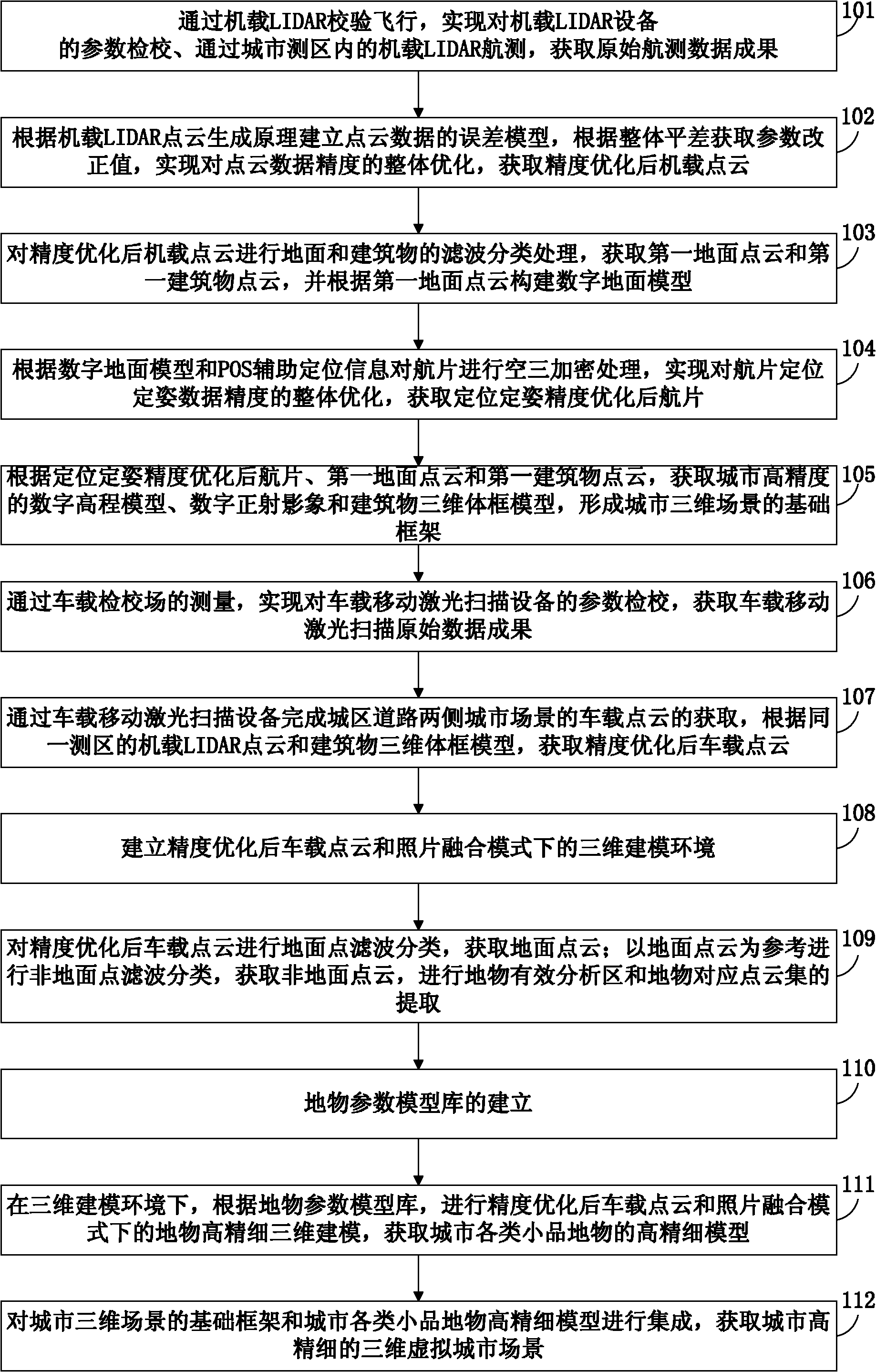
[0045] In order to improve development efficiency, reduce development costs, shorten development cycles and improve modeling precision, embodiments of the present invention provide a high-precision three-dimensional city modeling method, see figure 1 , See the description below for details:
[0046] 101: Through airborne LIDAR (Light Detection And Ranging, Lidar) verification flight, realize the parameter calibration of airborne LIDAR equipment, and obtain the original aerial survey data results through the airborne LIDAR aerial survey in the urban survey area;
[0047] Among them, the main components of the airborne LIDAR are laser sensors, digital cameras and POS positioning and attitude determination systems. The laser sensor needs to check heading (yaw angle), roll (roll angle) and pitch (pitch angle) three parameters; digital camera needs to check heading, roll, pitch and camera distortion parameters. The calibration of the parameters requires field measurement of ground control points, and professional data processing and analysis methods are used to solve the calibration parameters to remove the systematic errors in the measurement process. The calibration of laser sensors and digital cameras should be based on actual needs, select a calibration site that meets technical requirements, obtain initial point cloud data through laser sensors, obtain aerial photographs through digital cameras, and obtain required positioning and orientation data through POS positioning and orientation systems , Used for the solution of the initial point cloud and positioning and attitude of aerial photos.
[0048] Among them, through the airborne LIDAR aerial survey in the urban survey area, the results of obtaining the original aerial survey data are specifically: through the airborne LIDAR placed on the aircraft, the high-density 3D laser point cloud and high-resolution urban area are obtained according to the designed route plan. Digital photo. Among them, the side overlap of the laser point cloud should reach 30%, the course overlap of the aerial photos should reach 60%, and the side overlap should reach 30%.
[0049] 102: Establish an error model of point cloud data according to the principle of airborne LIDAR point cloud generation, obtain parameter correction values ​​according to the overall adjustment, realize the overall optimization of the accuracy of the point cloud data, and obtain the airborne point cloud after accuracy optimization;
[0050] Among them, this step is specifically: referring to the principle of airborne LIDAR point cloud generation, establishing an error model of point cloud data, taking the point cloud data in the adjacent or overlapping area of ​​the point cloud strip as a reference, and then referring to a small number of ground control points, according to The overall adjustment obtains the space coordinate parameters x, y and z, and the correction values ​​of the attitude parameters heading, roll and pitch. The parameters are corrected by the obtained parameter correction values ​​to realize the overall optimization of the initial point cloud data accuracy and obtain the accuracy Airborne point cloud after optimization.
[0051] 103: Perform ground and building filtering and classification processing on the airborne point cloud after accuracy optimization, obtain the first ground point cloud and the first building point cloud, and construct a digital ground model based on the first ground point cloud;
[0052] 104: According to the digital ground model and POS-assisted positioning information, the aerial photos are encrypted by air three to realize the overall optimization of the accuracy of the aerial photos positioning and attitude determination, and the aerial photos after the positioning and attitude accuracy optimization are obtained;
[0053] Among them, this step is specifically: according to the digital terrestrial model and POS auxiliary positioning information, the office collects the same-named points in the aerial photograph overlapping area of ​​the survey area, and performs the overall air three encryption of the survey area with reference to the digital terrestrial model. The POS auxiliary positioning information of each aerial photograph is optimized and corrected to remove local accidental errors, so as to realize the overall optimization of the aerial photograph positioning and attitude data accuracy, and obtain the aerial photograph after the positioning and attitude accuracy optimization.
[0054] 105: Optimized aerial photos, first ground point cloud and first building point cloud based on the positioning and attitude accuracy to obtain high-precision digital elevation models, digital orthophotos, and three-dimensional building frame models of the city to form a three-dimensional urban scene The basic framework;
[0055] Among them, obtaining the high-precision digital elevation model of the city specifically includes: manually editing and modifying the first ground point cloud to obtain the ground point cloud with the correct final classification; constructing a triangulation model for the ground point cloud with the final classification correct, and interpolating Then a high-precision digital elevation model of the city is formed. Among them, the filter classification method in the embodiment of the present invention is described by a mathematical morphological filter classification method. In specific implementation, other filter classification methods may also be used, which is not limited in the embodiment of the present invention.
[0056] Among them, the acquisition of digital orthophotos is specifically as follows: according to the city’s high-precision digital elevation model, refer to the aerial photos after the positioning and attitude accuracy is optimized, and perform digital differential correction on the aerial photos after the optimization of the positioning and attitude accuracy to obtain a differential correction image covering the surface. At the same time, determine the splicing plan of the differential correction image, and use the standard image frame to cut into a digital orthoimage.
[0057] Among them, obtaining the three-dimensional volume frame model of the building specifically includes: according to the first ground point cloud and the first building point cloud, the normal vector-based area growth method is used to achieve the segmentation of the building roof patch; the point cloud step feature and The intersection feature of the patch determines the initial feature structure line of the building roof; the aerial image is used to assist in optimizing the feature structure line of the building, and then a small amount of manual editing is performed to determine all the correct feature structure lines corresponding to the building model; the split and merge method is adopted Automatically construct and generate a three-dimensional volume frame model of the building model.
[0058] 106: Realize the parameter calibration of the vehicle-mounted mobile laser scanning equipment through the measurement of the vehicle-mounted inspection and calibration field, and obtain the original data results of the vehicle-mounted mobile laser scanning;
[0059] Like the airborne LIDAR equipment introduced above, the main components of the vehicle-mounted mobile laser scanning equipment are laser sensors, digital cameras and POS positioning and attitude determination systems, with the same technical principles. The main difference between the two devices is the mobile carrier they carry. Airborne LIDAR equipment works by placing it on an airplane; vehicle-mounted mobile laser scanning measurement equipment works by placing it on the roof of a car. In the open area, select the building inspection and calibration site that meets the technical requirements. The field business collects point clouds and photos, and the internal business conducts data processing and analysis to complete the precise inspection and calibration of the on-board equipment laser sensors and digital cameras.
[0060] 107: Use the vehicle-mounted mobile laser scanning equipment to obtain the vehicle-mounted point cloud of the urban scenes on both sides of the urban road, and obtain the vehicle-mounted point cloud after the accuracy optimization according to the airborne LIDAR point cloud and the three-dimensional volume model of the building in the same survey area;
[0061] In urban surveying areas, especially urban high-rise areas, the GPS observation environment is very unsatisfactory. When the vehicle-mounted mobile laser scanning measurement is used for data collection, the data accuracy of POS positioning and attitude determination is not ideal, resulting in the point cloud obtained on the plane and elevation. Great error. Therefore, it is necessary to combine the characteristics of vehicle-mounted mobile laser scanning measurement data collection to establish a technical method for optimizing the accuracy of the vehicle-mounted point cloud to ensure the accuracy of the model extracted later.
[0062] Among them, the vehicle-mounted point cloud after obtaining accuracy optimization is specifically:
[0063] 1) Refer to the airborne LIDAR point cloud in the same survey area to determine the elevation accuracy of the vehicle-mounted mobile laser scanning measurement data, and optimize the vehicle-mounted point cloud elevation accuracy;
[0064] The specific steps are:
[0065] Taking the airborne LIDAR point cloud in the same survey area as the reference for elevation control, the vehicle-mounted point cloud is evaluated for the elevation accuracy along the direction of the car's trajectory, and the elevation correction model based on the direction of the car's trajectory is established to optimize the elevation accuracy of the on-board point cloud. Among them, all vehicle-mounted point cloud elevation accuracy is optimized, based on the correction value of the nearest control point around, and the interpolation method is used to complete the vehicle-mounted point cloud elevation correction. The embodiment of the present invention takes a linear interpolation method as an example for description. During specific implementation, other interpolation methods may also be used, which is not limited in the embodiment of the present invention.
[0066] 2) Refer to the three-dimensional volume frame model of the building in the same survey area to optimize the plane accuracy of the vehicle-mounted point cloud, and obtain the vehicle-mounted point cloud after the accuracy is optimized.
[0067] The specific steps are:
[0068] For the vehicle-mounted point cloud whose plane accuracy exceeds the limit in the urban survey area, refer to the three-dimensional volume frame model of the building, and evenly select some building feature points as the reference control point for the optimization of the vehicle-mounted point cloud plane accuracy;
[0069] Select the corresponding points of the reference control points on the vehicle-mounted point cloud in the urban survey area, and establish the corresponding set of the characteristic points on the vehicle-mounted point cloud and the reference control points;
[0070] Taking the real position of the reference control point as the constraint condition, taking the six variables of x, y, z, heading, roll and piteh as the observation variables, establish the observation equation, and use the least squares adjustment method to solve the correction values ​​of the six variables. Optimize six variables, recalculate the vehicle-mounted point cloud, optimize the plane accuracy of the vehicle-mounted point cloud, and obtain the vehicle-mounted point cloud after the accuracy optimization.
[0071] Among them, the establishment of the observation equation refers to the relevant theoretical formulas of surveying and makes improvements, so I will not repeat them here.
[0072] 108: Establish a 3D modeling environment in the vehicle-mounted point cloud and photo fusion mode after accuracy optimization;
[0073] In the urban measurement area, the points of the same name are selected for the vehicle-mounted photos, and the panoramic photo map moving along the measurement trajectory in the urban measurement area is established according to the panorama construction principle, and the corresponding relationship between the panoramic photo image and the vehicle-mounted photo is initially established. That is, after manually clicking to determine the location in the panoramic photo map, the photo details on the vehicle photo can be found according to the location. At the same time, it is also necessary to establish the match between the vehicle photo and the vehicle point cloud after the accuracy optimization in the two-dimensional image space, that is, after determining a vehicle photo, the computer automatically finds the corresponding accuracy optimization vehicle point cloud, that is, referring to the POS positioning and attitude information. Realize the precise matching of on-board point cloud and on-board photos after precision optimization.
[0074] The formula for matching the on-board point cloud and the on-board photo after the accuracy optimization is realized, refers to the collinear equation in photogrammetry, and improves on this basis, as follows:
[0075] x=-f(a 1 (X-X s )+b 1 (Y-Y s )+c 1 (Z-Z s ))/(a 3 (X-X s )+b 3 (Y-Y s )+c 3 (Z-Z s ))
[0076] y=-f(a 2 (X-X s )+b 2 (Y-Y s )+c 2 (Z-Z s ))/a 3 (X-X s )+b 3 (Y-Y s )+c 3 (Z-Z s ))
[0077] Where a 1 =cos Ψcos κ-sin Ψsinωsin κ
[0078] a 2 =-cos Ψsin κ-sin Ψsinωcos κ
[0079] a 3 =-sin Ψcosω
[0080] b 1 =cosωsin κ
[0081] b 2 =cosωcos κ
[0082] b 3 =-sinω
[0083] c 1 =sin Ψcos κ+cos Ψsinωsin κ
[0084] c 2 =-sin Ψsin κ+cos Ψsinωcos κ
[0085] c 3 =cos Ψcosω
[0086] Among them, x and y are the coordinates of the image point, X, Y, and Z are the coordinates of the corresponding ground points, Xs, Ys, and Zs are the coordinates of the projection center in the object space coordinate system, f is the camera principal distance, Ψ, ω And κ are the three attitude positioning angles corresponding to the Chinese and foreign azimuth elements in photogrammetry. Through the above processing, a 3D modeling environment in the vehicle-mounted point cloud and photo fusion mode after accuracy optimization can be established.
[0087] 109: Perform ground point filtering and classification on the vehicle-mounted point cloud after accuracy optimization to obtain ground point clouds; use the ground point cloud as a reference to perform non-ground point filtering and classification to obtain non-ground point clouds, and perform ground object effective analysis area and ground object corresponding points Yunji extraction;
[0088] Among them, the filtering and classification processing of non-ground points is specifically as follows: if the average elevation difference between the elevation of the non-ground point and the surrounding ground point within the second threshold range is greater than the first threshold, it will be regarded as the non-ground feature corresponding point and as the potential analysis point of the ground feature .
[0089] After obtaining the non-ground point cloud, it is necessary to analyze the effective ground object points. The effective ground object point analysis method is: if there are more than the fourth threshold in the third threshold range around the potential ground object corresponding point Point, the corresponding point of the potential feature is a valid feature point, and the regional growth method is used to perform the cluster classification and identification of the feature point cloud; otherwise, it is a noise point.
[0090] Among them, the values ​​of the first threshold, the second threshold, the third threshold, and the fourth threshold are set according to actual application needs, and the embodiment of the present invention does not limit this during specific implementation.
[0091] 110: Establishment of ground feature parameter model library;
[0092] According to the structural characteristics of urban features and the requirements of modeling precision, the classification of feature models, mainly including street lights, street signs, fences, bus stop signs, etc. According to the structural characteristics of urban sketch elements, different model parameter libraries are defined for similar features according to different structures, and ID type numbers are established.
[0093] Taking the corresponding traffic lights on the common sidewalks in cities as an example, the traffic lights are one of the traffic lights in the city. According to the structural characteristics of the traffic lights, the model parameter library is described by defining the following parameters to assist the computer to automatically complete the generation of the vector model. The model parameter library of the traffic lights is defined as follows: model type number, model center x, y and z coordinates, The height of the pillar at the bottom of the model, the pillar type, the pillar radius (such as the circle type), the length of the traffic light display, the width of the traffic light display, and the thickness of the traffic light display.
[0094] 111: In the 3D modeling environment, according to the feature parameter model library, the accuracy is optimized and the high-precision 3D modeling of the features in the vehicle-mounted point cloud and photo fusion mode is used to obtain high-precision models of various urban features;
[0095] 1) The main view adopts the photo panoramic view display mode;
[0096] By adopting the photo panoramic view mode display, it is convenient to clearly identify the features on both sides of the road.
[0097] 2) The auxiliary view adopts the partial zoom display mode of the original photo and the point cloud profile display mode;
[0098] Among them, there are two types of auxiliary views, including photo auxiliary view and point cloud auxiliary view. The photo auxiliary view adopts a partial zoom display mode of the original photo to facilitate the clear identification of feature elements; the point cloud auxiliary view adopts the point cloud profile display mode , And combined with photo information to assist manual further identification; and to facilitate detailed identification of the model shape and structure.
[0099] 3) Click on the focus feature in the photo panoramic view, the computer will automatically display multiple photos corresponding to the focus feature in the auxiliary view; manually click the focus feature to display the clearest auxiliary view and photo; finally, the computer will automatically search for the focus feature The effective point cloud set corresponding to the object, and the accurate matching of the vehicle-mounted point cloud and the photo in the two-dimensional image space after the accuracy optimization is realized;
[0100] 4) The computer automatically searches for all the effective point cloud sets corresponding to the ground feature of interest in the effective analysis area of ​​the ground feature, and obtains the number of effective point cloud sets. When the number of effective point cloud sets is one, the effective point cloud set is the correct point cloud set; When the number of cloud sets is not one, use multiple auxiliary views to assist in the display, and determine the correct point cloud set through manual interaction;
[0101] Among them, the computer automatically searches for all the effective point cloud sets corresponding to the concerned feature in the effective analysis area of ​​the feature, specifically:
[0102] Refer to the photogrammetric collinear equation to project the effective feature points in the effective analysis area into the two-dimensional image space;
[0103] Take the manually determined position on the photo as the center and draw a circle with the fifth threshold as the radius, as the first analysis area for searching effective point cloud sets in the two-dimensional image space, and analyze the effective point cloud concentration points in the first analysis area Type, to identify the type of the point cloud in the first analysis area, and determine all valid point cloud sets.
[0104] Among them, in the first analysis area to analyze the types of effective point cloud concentration points, the analysis method adopted is specifically: clustering analysis is performed using the three-dimensional distance between the points in the effective point cloud concentration as the sixth threshold. During specific implementation, other analysis methods may also be used, which is not limited in the embodiment of the present invention.
[0105] Wherein, the values ​​of the fifth threshold and the sixth threshold are set according to the needs in actual applications, and during specific implementation, the embodiment of the present invention does not limit this.
[0106] 5) After manual identification with reference to the photos and the vehicle-mounted point cloud information after the accuracy optimization, the cut section displays the vehicle-mounted point cloud after the accuracy optimization, and on the vehicle-mounted point cloud after the accuracy optimization, the parameters are defined according to the parameters in the ground object parameter model library. Perform parameter measurement in order to obtain parameter information;
[0107] 6) The computer saves the parameter information, and automatically completes the generation of high-precision models of various sketches in the city.
[0108] 112: Integrate the basic framework of the city's three-dimensional scene and the high-precision model of various sketches and features of the city to obtain the city's high-precision three-dimensional virtual city scene.
[0109] To sum up, the embodiments of the present invention provide a high-precision three-dimensional urban modeling method, which improves development efficiency, reduces development costs, shortens the development cycle, improves modeling precision, and satisfies practical application requirements. need.
[0110] Those skilled in the art can understand that the accompanying drawings are only schematic diagrams of a preferred embodiment, and the serial numbers of the above-mentioned embodiments of the present invention are only for description, and do not represent the advantages and disadvantages of the embodiments.
[0111] The above descriptions are only preferred embodiments of the present invention and are not intended to limit the present invention. Any modification, equivalent replacement, improvement, etc. made within the spirit and principle of the present invention shall be included in the protection of the present invention. Within range.

PUM

no PUM

Description & Claims & Application Information

We can also present the details of the Description, Claims and Application information to help users get a comprehensive understanding of the technical details of the patent, such as background art, summary of invention, brief description of drawings, description of embodiments, and other original content. On the other hand, users can also determine the specific scope of protection of the technology through the list of claims; as well as understand the changes in the life cycle of the technology with the presentation of the patent timeline. Login to view more.

Similar technology patents

Classification and recommendation of technical efficacy words

  • High precision
  • High degree of automation

Full-automatic flexible assembly line of light emitting diode (LED) bulb lamp

InactiveCN102896494AIncreased reliability and automationHigh degree of automationAssembly machinesLight sourceStructure based
Owner:SHANGHAI RADIO EQUIP RES INST
Why Eureka
Try Eureka