Low-speed and zero-speed rotor position observation method and device during fault-tolerant operation of synchronous motor

A technology of synchronous motor and rotor position, which is applied in the control of electromechanical transmission, motor generator control, electronic commutation motor control, etc. It can solve the problem of less sensorless technology of synchronous motor, and achieve the expansion of operating speed range and good real-time performance. , the effect of algorithm simplification

Inactive Publication Date: 2011-05-25
FUZHOU UNIV
View PDF1 Cites 29 Cited by
  • Summary
  • Abstract
  • Description
  • Claims
  • Application Information

AI Technical Summary

Problems solved by technology

Scholars have conducted detailed research on the fault-tolerant topology and control principles of synchronous motors, and conducted extensive and in-depth research on the sensorless control technology of synchronous moto...

Method used


Image

  • Low-speed and zero-speed rotor position observation method and device during fault-tolerant operation of synchronous motor
  • Low-speed and zero-speed rotor position observation method and device during fault-tolerant operation of synchronous motor
  • Low-speed and zero-speed rotor position observation method and device during fault-tolerant operation of synchronous motor

Examples


Embodiment Construction

[0020] Now take the open circuit of the C-phase winding of the motor as an example, and describe it as follows.

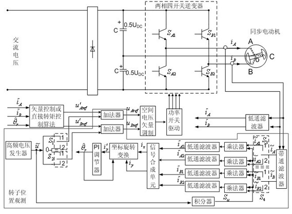
[0021] The control principle block diagram of the inventive method is as figure 1 shown. The AC voltage is rectified by a diode, and then filtered into a DC voltage by two equal-capacity capacitors C Finally, it is added to the two-phase four-switch inverter that controls the two-phase winding voltage of the synchronous motor. The midpoint O of the two-phase winding of the motor is connected to the midpoint of the two capacitors. Sampling value of two-phase winding current of synchronous motor , The fundamental component is output after being filtered by a low-pass filter , ;Vector control or direct torque control algorithm link according to the input current fundamental wave component , and rotor position angle , calculate the given initial value of the stator two-phase winding voltage , ; If there is no rotor position observation link, , ...


PUM


Abstract

The invention relates to a low-speed and zero-speed rotor position observation method and a low-speed and zero-speed rotor position observation device during fault-tolerant operation of a synchronous motor. The low-speed and zero-speed rotor position observation method during fault-tolerant operation of the synchronous motor is characterized in that: high frequency sine pulse voltage with fixed frequency is applied at a two-phase working winding end at partial time intervals, and the working winding generates corresponding high frequency current; and the high frequency current is synchronously acquired by a band-pass filter, a rotor position angle observation error function is calculated through links such as a multiplier, a low pass filter, an adder, a coordinate rotation transformation and the like, a value of the error function is sent to a proportional-integral (PI) regulator, and an observation value of the rotor position angle is output by the PI regulator. The invention is favorable for accurately observing the rotor position during the fault-tolerant operation of a three-phase salient pole synchronous motor under the condition that one phase of stator winding is open-circuit.

Description

technical field [0001] The invention relates to a drive control of a synchronous motor, in particular to a method and a device for detecting the rotor position of the synchronous motor. Background technique [0002] Synchronous motors are divided into electrically excited synchronous motors and permanent magnet synchronous motors. By adjusting the excitation current of the rotor of the electrically excited synchronous motor, the unit power factor operation of the stator side of the motor can be realized, and the high-efficiency operation of the motor can be realized. The rotor of the permanent magnet synchronous motor is excited by permanent magnets, which does not require a separate excitation winding. The motor has a compact structure and can operate with high power factor and high efficiency. In view of the high efficiency advantages of the above two motors, synchronous motors have been widely used in both ground industry and aerospace. For example, a large number of sy...

Claims


Application Information

Patent Timeline
IPC IPC(8): H02P6/16H02P21/14H02P21/18
Inventor 周扬忠周建红许海军
Owner FUZHOU UNIV
Why Eureka
Try Eureka