Hydraulic system of a transmission unit, comprising a main transmission pump and an auxiliary pump

A hydraulic system and transmission technology, applied in transmission control, transmission parts, transportation and packaging, etc., can solve problems such as unreachable, ISG clutch cannot be closed, internal combustion engine cannot start automatically, etc., and achieve the effect of simple cost

Inactive Publication Date: 2011-05-25
ZF FRIEDRICHSHAFEN AG
View PDF5 Cites 23 Cited by
  • Summary
  • Abstract
  • Description
  • Claims
  • Application Information

AI Technical Summary

Problems solved by technology

[0011] The desired delivery rate provided by the auxiliary pump for supplying the primary pressure circuit and, if necessary, for supplying the secondary pressure circuit cannot be achieved at such a low voltage of the accumulator that the ISG clutch cannot be engaged and the internal combustion engine cannot be started automatically

Method used


Image

  • Hydraulic system of a transmission unit, comprising a main transmission pump and an auxiliary pump
  • Hydraulic system of a transmission unit, comprising a main transmission pump and an auxiliary pump
  • Hydraulic system of a transmission unit, comprising a main transmission pump and an auxiliary pump

Examples


Embodiment Construction

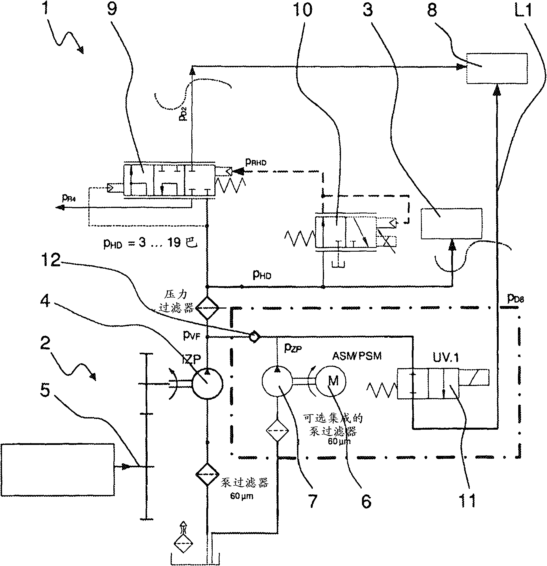
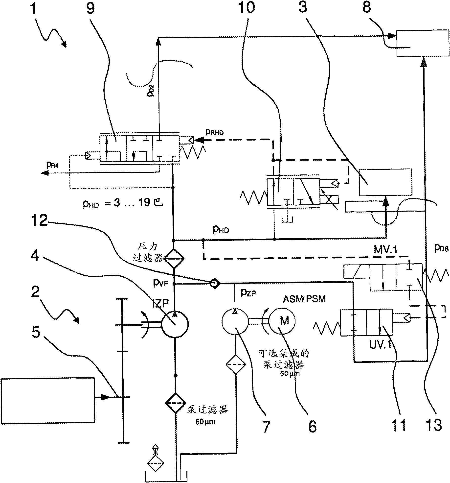
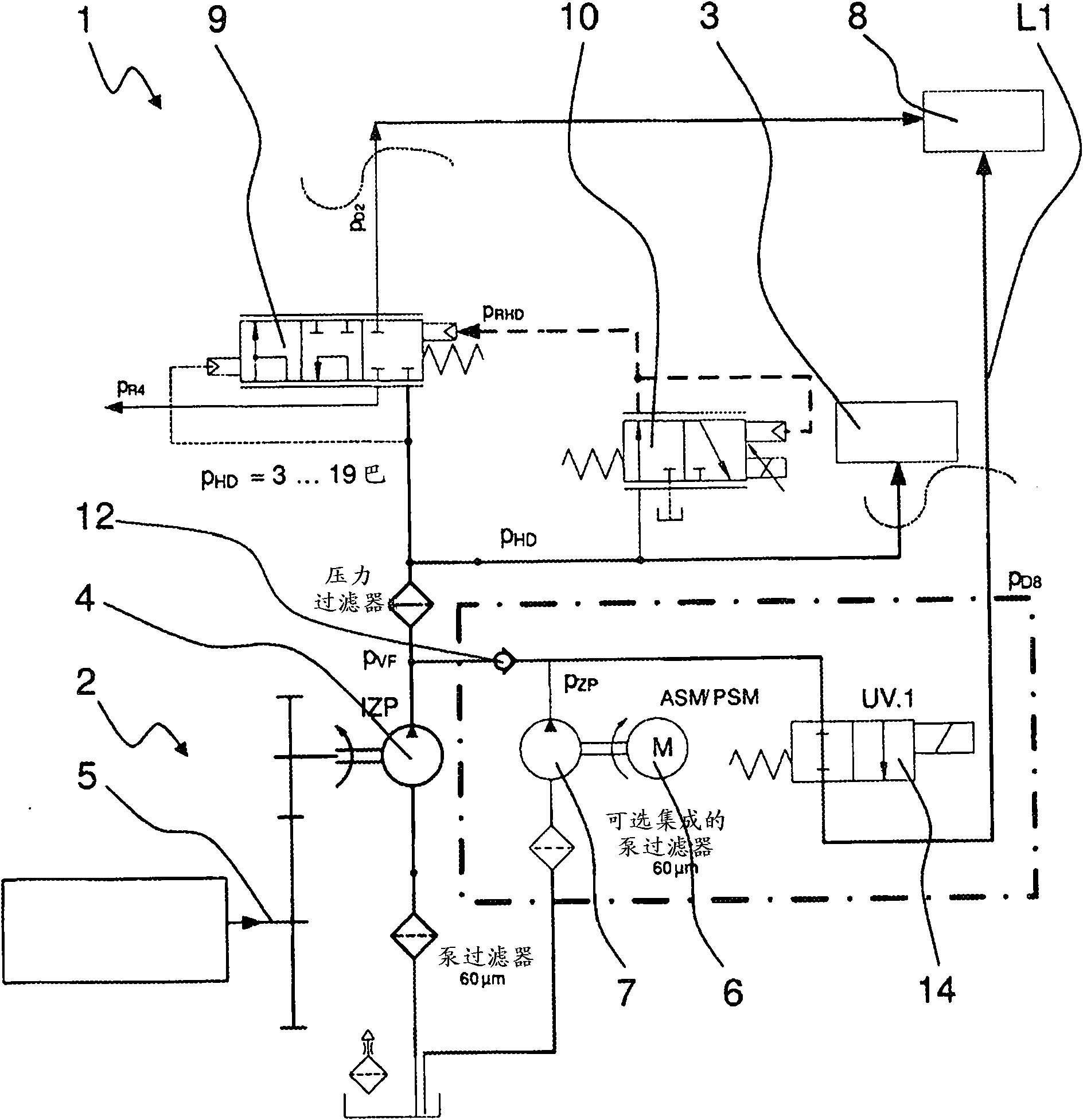
[0032] figure 1 A greatly simplified schematic diagram of the hydraulic system 1 of the transmission device of the vehicle or the powertrain of the vehicle is shown. The vehicle is provided with a hybrid drive device in a known manner. The hybrid drive device includes a power device configured as an internal combustion engine, an electric motor 6 and a transmission device 2. The transmission device 2 can in principle be any known automated manual transmission or automatic transmission in practice, which is provided with hydraulically controllable shift elements such as friction-locked shift clutches or disc brakes and can also be applied to commercial applications Vehicles such as public vehicles or similar vehicles.

[0033] In the transmission device 2, a plurality of shift elements that can be hydraulically controlled by the hydraulic system 1 can generate a force transmission chain, and the shift elements can be loaded with operating pressure through the primary pressure cycl...


PUM


Abstract

The invention relates to a hydraulic system (1) of a transmission unit (2) comprising a main transmission pump which can be driven by a torque applied via the transmission unit and an auxiliary pump (7) which can be driven by an electrical machine (6), the two pumps supplying a primary pressure circuit (3) and a secondary pressure circuit (8) with hydraulic fluid depending on the operational state. A pressure side of the main transmission pump and a pressure side of the auxiliary pump (7) are connected to the primary pressure circuit (3) upstream of a pressure relief valve (9) which adjusts a main pressure (pHD) of the primary pressure circuit (3). The pressure relief valve (9) is arranged between the pressure sides of the main transmission pump (4) and the auxiliary pump (7) and the secondary pressure circuit (8). The pressure side of the auxiliary pump (7) can be actively connected to the secondary pressure circuit (8) via a hydraulic line (L1) which can be blocked in the direction of the primary pressure circuit (3) and the secondary pressure circuit (8) and which by-passes the pressure relief valve (8).

Description

Technical field [0001] The invention relates to a hydraulic system of a transmission device with a transmission main pump and an auxiliary pump according to the type defined in more detail in the preamble of claim 1, and a type defined in more detail in the preamble of claim 8. The method used to operate this hydraulic system. Background technique [0002] In order to be able to reduce the consumption and emission of harmful substances in vehicles equipped with internal combustion engines and known from practice, internal combustion engines are shut down in suitable vehicle operating states in various vehicle designs. In addition, this function is called an engine start-stop function, which is activated or deactivated depending on the operating state of various vehicle components and triggers the shutdown of the internal combustion engine even in a short-term parking state. [0003] In order to prevent the general vehicle operation from being affected by the engine start-stop func...

Claims


Application Information

Patent Timeline
Patent Type & Authority Applications(China)
IPC IPC(8): F16H61/00F16H57/04
CPCF16H61/0031F16H57/0446F16H2312/14F16H2061/0037Y10T137/0396Y10T137/85978
Inventor M·巴赫曼K·博恩特雷格R·布达赫B·胡诺尔德
Owner ZF FRIEDRICHSHAFEN AG
Why Eureka
Try Eureka