Nutation oscillating-tooth speed reducer

A movable tooth deceleration and movable tooth technology, applied in the direction of transmission, transmission parts, gear transmission, etc., can solve the problems of low transmission efficiency, low bearing capacity, complex structure, etc., achieve high bearing capacity, reduce the number of parts, The effect of reducing the size of the mechanism

Inactive Publication Date: 2011-06-01
DALIAN JIAOTONG UNIVERSITY
View PDF5 Cites 4 Cited by
  • Summary
  • Abstract
  • Description
  • Claims
  • Application Information

AI Technical Summary

Problems solved by technology

The nutating movable tooth reduction device not only solves the problems of complex structure, large volume, low transmission efficiency and low load-carrying capacity of similar

Method used


Image

  • Nutation oscillating-tooth speed reducer
  • Nutation oscillating-tooth speed reducer
  • Nutation oscillating-tooth speed reducer

Examples


Embodiment Construction

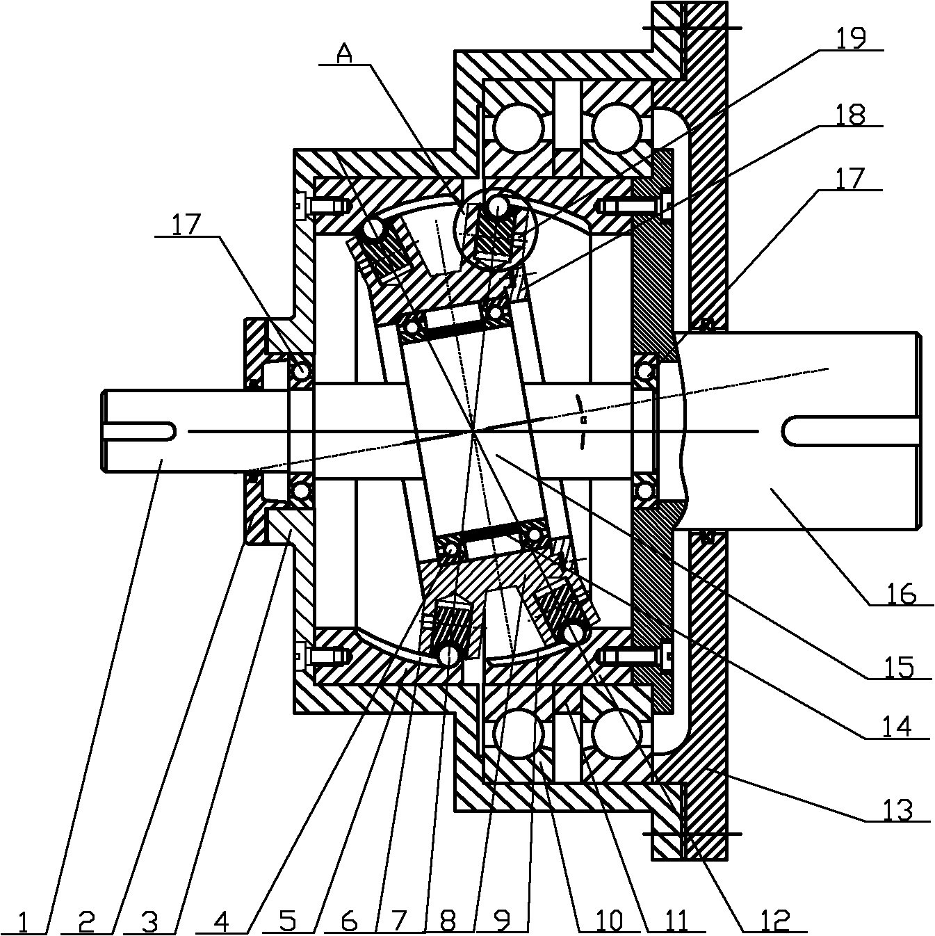
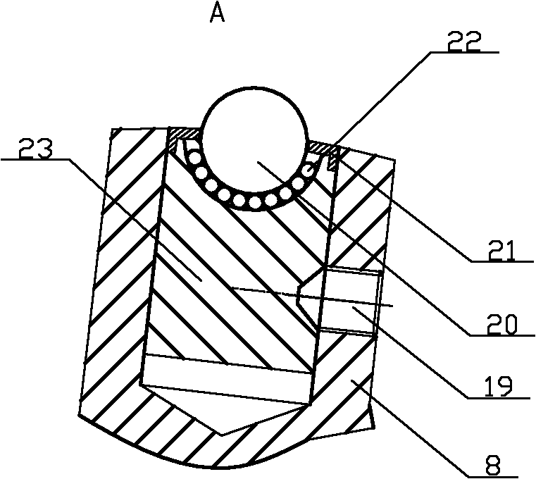
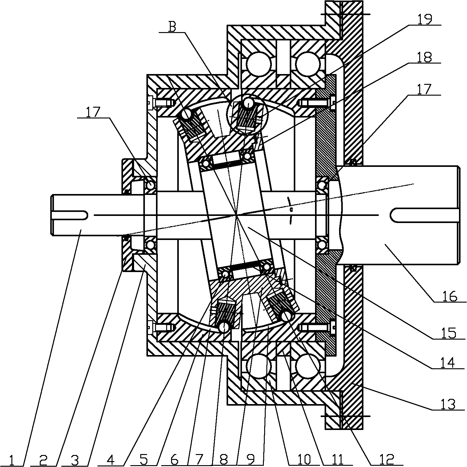
[0024] figure 1 , 2Shown is one of the embodiments of the present invention, it is two bulls-eye type ball rolling pairs 7 in the fixed disk tooth groove 6 and the rotating disk tooth groove 9 adopting closed meshing transmission nutating movable tooth reduction device; Its structure includes machine base 3, input shaft 1, support bearing 17, fixed disk 5, rotating disk 12, rotating disk bearing 10, nutating disk movable tooth transmission mechanism, output shaft end cover 13 and output shaft 16; Support bearing end cover 2, support bearing 17, fixed disc 5, rotating disc 12, output shaft 16 and output shaft end cover 13 connected with rotating disc 12 are installed in the shaft hole of input end in sequence; 3 Two rotating disk bearings 10 are installed on the rotating disk 12 between the inner walls, and a rotating disk sleeve 11 is arranged on the rotating disk between the two rotating disk bearings 10, and one end of the input shaft 1 is connected to the On the motor sha...


PUM


Abstract

The invention belongs to speed reducers, and specifically relates to a nutation oscillating-tooth speed reducer. The nutation oscillating-tooth speed reducer is characterized in that a bull-eye type nutation-disc oscillating-tooth transmission mechanism comprises a nutation disc, a nutation bearing, a bearing sleeve, an end cover, bull-eye type round-ball rolling pair sets, a fixed disc tooth slot and a rotating disc tooth slot; each bull-eye type round-ball rolling pair set is formed by arraying a plurality of bull-eye type round-ball rolling pairs; and each bull-eye type round-ball rolling pair consists of a round ball, a round ball check ring, a rolling ball and an oscillating-tooth main body. The speed reducer is reasonable, novel and special in design, has a compact structure, can solve the problem that the similar speed reducer has a complex structure, large volume and low transmission efficiency, and also can prevent the defect of top cutting generated when the transmission ratio is great; and simultaneously, the speed reducer has the characteristics of high transmission precision, high transmission rigidity, high transmission efficiency, low noise, big transmission ratio, long service life, few parts, small volume, light weight, convenience for installment, manufacturing and maintenance, good bearing capability, no need of output mechanisms, and the like.

Description

technical field [0001] The invention belongs to a speed reducer, in particular to a nutating movable tooth speed reduction device. Background technique [0002] In the mechanical field, the traditional transmission method adopts gear transmission; its meshing teeth are usually in the form of fixed teeth, and in this way a certain clearance must be reserved for meshing. Due to the existence of gaps, the requirements of the prior art for high load capacity, high precision, high reliability, large speed ratio, and small-volume mechanical transmission cannot be met. In order to eliminate the backlash and make up for the deficiency of conventional gear transmission, a movable meshing gear transmission method is adopted at this stage, which can realize zero-backlash transmission. In recent years, the movable tooth transmission mechanism has also been deeply discussed and researched and developed at home and abroad. The applicant once applied to the State Intellectual Property Of...

Claims


Application Information

Patent Timeline
IPC IPC(8): F16H1/32F16H57/02F16H57/028
Inventor 王广欣朱莉莉
Owner DALIAN JIAOTONG UNIVERSITY
Why Eureka
Try Eureka