Electric air conditioning device for bus
A technology of electric air conditioners and air conditioners, which is applied to lighting and heating equipment, compressors, refrigeration safety arrangements, etc., can solve the problems of low efficiency, poor adjustability, and unfavorable assembly of bus air conditioners, so as to improve energy utilization and reduce weight , the effect of reducing pollution
- Summary
- Abstract
- Description
- Claims
- Application Information
AI Technical Summary
Problems solved by technology
Method used
Image
Examples
Embodiment 1
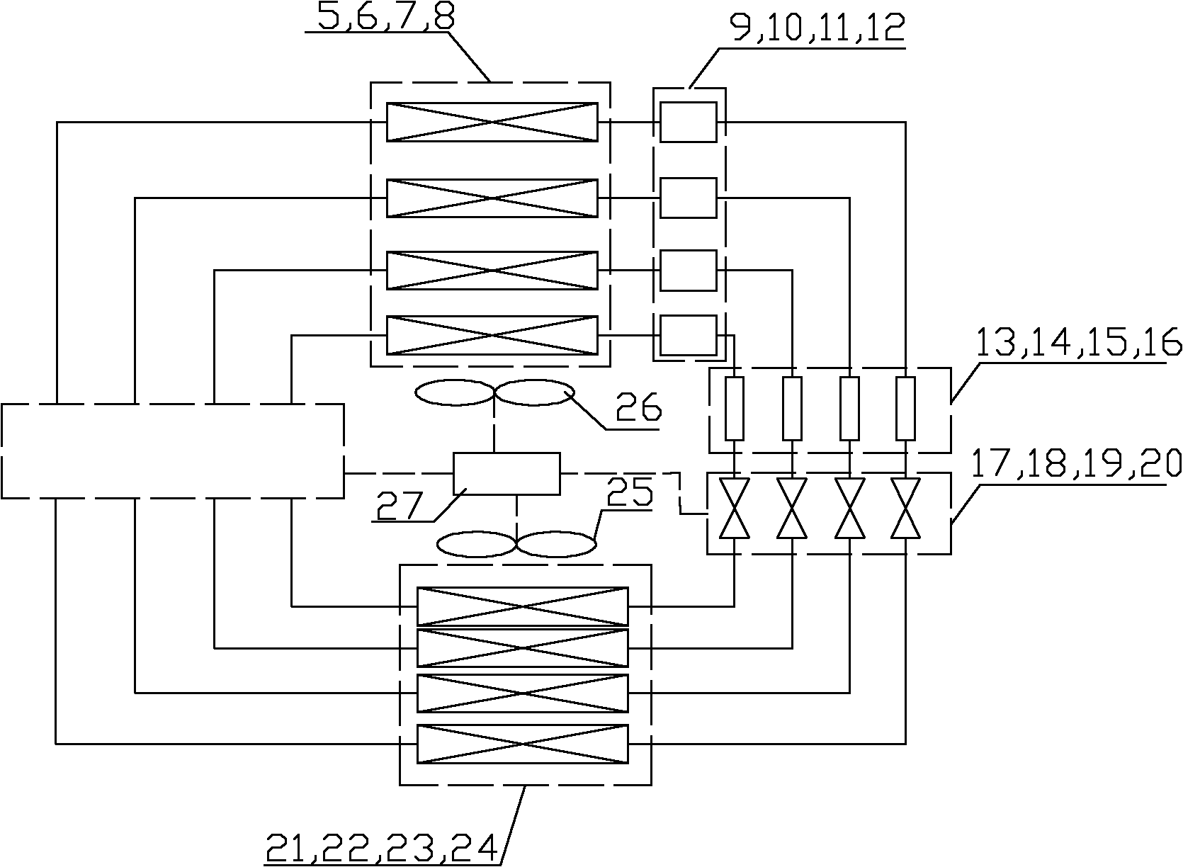
[0032] refer to figure 1 , an electric air-conditioning device for a bus, comprising an electric compressor and at least two sets of refrigeration cycle units arranged in parallel, the refrigeration cycle unit comprising a group of condensers, a group of liquid storage tanks, a group of dry filters, A group of throttling mechanisms and a group of evaporators, the group of evaporators is connected to the electric compressor, the electric compressor is connected to the group of condensers, and a group of condensers of each refrigeration cycle unit passes through The air duct is connected to the condensing fan unit, and a group of evaporators of each refrigeration cycle unit is connected to the evaporator fan unit through the air duct. The electric compressor, condensing fan unit, evaporator fan unit and each refrigeration cycle unit are connected to The energy output mode selectively starts the controller connection of each group of refrigeration cycle units, condensing fan unit...
Embodiment 2
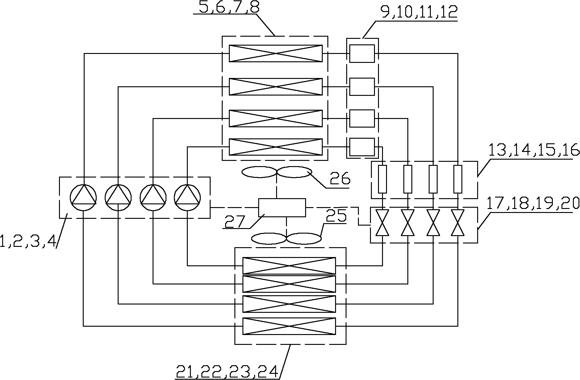
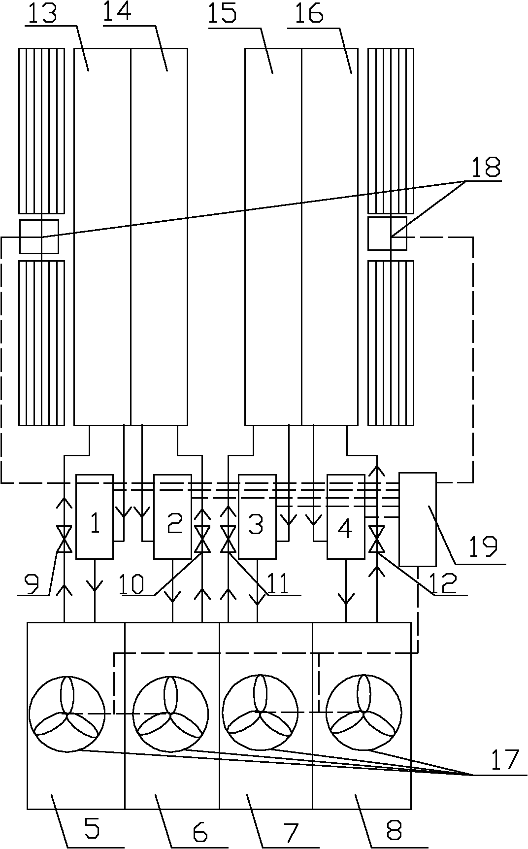
[0041] refer to figure 2 and image 3 , in this embodiment, the electric compressor includes at least two groups of compressor units arranged in parallel, the number of the compressor units is the same with respect to the refrigeration cycle unit, one group of compressor units and one group of refrigeration cycle units A group of evaporators and a group of condensers are connected. Other structures of this embodiment are the same as those of Embodiment 1.
[0042] In this example, if figure 2 As shown, it is a schematic diagram of the operation scheme of four sets of systems. When four compressors are used, the electric compressors (1, 2, 3, 4) independently drive the respective condensers (5, 6, 7, 8), liquid storage tanks (9, 10, 11, 12), dry filter (13, 14, 15, 16), throttling mechanism (17, 18, 19, 20) and independent evaporator (21, 22, 23, 24), constitute 4 independent refrigeration cycles unit, the condensing fan system 25 is shared by the condensers of each inde...
Embodiment 3
[0045] refer to Figure 4 , when two compressors are used, the compressors (1, 2) independently drive their respective condensers (3, 4), throttling mechanisms (5, 6) and independent evaporators (7, 8) , forming two independent refrigeration cycle units, the condensing fan system 10 is shared by the condensers of each independent system, the evaporation fan system 11 is shared by the evaporators of each independent system, and the control of the entire air conditioning system is controlled by a shared controller 12 and related elements The components are composed together to control the work of each working part of the air conditioning system. When the heat load in the car is small, one set of refrigeration system can be used to work. When the heat load in the car is large, two sets of independent systems can be used to operate. To carry out work, when one set and two sets of systems are put into work, it is equivalent to the output of the entire air conditioning system at 50%...
PUM
 Abstract
Description
Claims
Application Information
 - R&D
- Intellectual Property
- Life Sciences
- Materials
- Tech Scout
- Unparalleled Data Quality
- Higher Quality Content
- 60% Fewer Hallucinations
Browse by: Latest US Patents, China's latest patents, Technical Efficacy Thesaurus, Application Domain, Technology Topic, Popular Technical Reports.
© 2025 PatSnap. All rights reserved.Legal|Privacy policy|Modern Slavery Act Transparency Statement|Sitemap|About US| Contact US: help@patsnap.com


