
Method for controlling double-feed wind driven generator under imbalanced power grid voltage

A technology for wind turbines and grid voltage, which is used in motor generator control, electronic commutation motor control, and generator control, and can solve problems such as single control target and inability to convert control targets.

Inactive Publication Date: 2011-06-01
TIANJIN UNIV
View PDF4 Cites 37 Cited by
  • Summary
  • Abstract
  • Description
  • Claims
  • Application Information

AI Technical Summary

Problems solved by technology

However, compared with the dual synchronous rotating coordinate system control method, its control target is single, and the control target cannot be converted

Method used


Image

  • Method for controlling double-feed wind driven generator under imbalanced power grid voltage
  • Method for controlling double-feed wind driven generator under imbalanced power grid voltage
  • Method for controlling double-feed wind driven generator under imbalanced power grid voltage

Examples


Embodiment Construction

[0022] The present invention will be further described below in conjunction with the accompanying drawings and embodiments.

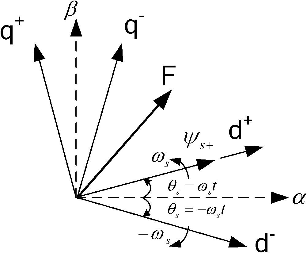
[0023] In the case of unbalanced grid voltage, a DFIG system with three-phase symmetry and mid-point isolation can be considered to have no zero-sequence component. The three-phase voltage, current and flux linkage can be decomposed into positive and negative sequence components in the stationary αβ coordinate system:

[0024]

[0025]

[0026] In the formula: F stands for voltage, current or flux linkage; are the initial phases of positive and negative sequence components respectively; ω s is the synchronous rotation angular velocity; the subscripts + and - correspond to positive and negative sequence components, respectively.

[0027] Such as figure 1 The stationary αβ coordinate system shown rotates dq synchronously with forward and reverse + , dq - Coordinate system, its conversion relationship is:

[0028] ...


PUM


Abstract

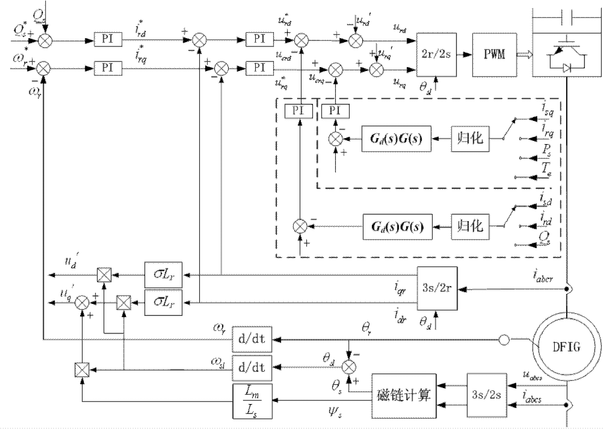
The invention belongs to the field of control over a power conversion device for a wind driven generator and relates to a method for controlling current switching of a double-feed wind driven generator rotor under an imbalanced power grid voltage. The method comprises the following steps of: calculating a stator voltage, a stator current and a rotor current under a two-phase static coordinate system; calculating stator voltages and stator currents of a d axis and a q axis under a flux linkage and a synchronous rotation coordinate system; calculating a slip angle and a slip angular velocity; calculating rotor currents of the d axis and the q axis under the rotation coordinate system; calculating stator active power, reactive power and electromagnetic torque; calculating rotor decoupling compensating voltage; naturalizing and calculating corresponding control variables, acquiring a secondary pulse actual value of a controlled variable through a bandpass filter and a lead lag link, subtracting the actual value from a secondary pulse given value, and calculating to acquire a two-time frequency compensation item through a proportional integral (PI) controller; calculating the given value of the rotor current of the d axis under the rotation coordinate system; allowing the difference of a rotation speed given value and a rotational angular velocity actual value to pass through the PI controller, and calculating to acquire the given value of the rotor current of the q axis under the rotation coordinate system; calculating to acquire reference values of rotor voltages of the d axis and the q axis under the rotation coordinate system; and calculating the rotor voltage under the rotor two-phase static coordinate system and generating switch signals which control power devices.

Description

technical field [0001] The invention relates to a control method for a rotor-side inverter of a doubly-fed wind power generator (DFIG) under unbalanced grid voltage, and belongs to the field of wind power generator control. Background technique [0002] The variable-speed wind turbine based on the doubly-fed induction generator (DFIG) has become the mainstream model in the world wind power market due to its high energy conversion efficiency and independent adjustment of active and reactive power. The stator side of DFIG is directly connected to the grid and is very sensitive to grid faults. A small unbalanced voltage will cause severe oscillation of active and reactive power, generator torque ripple, stator current imbalance and other problems. In addition, due to the strong coupling between the rotor and the stator, the unbalanced stator current will cause the rotor current to fluctuate, which will affect the operating state of the DFIG. When the grid voltage imbalance re...

Claims


Application Information

Patent Timeline
IPC IPC(8): H02P21/14H02P21/18
Inventor 夏长亮王萌史婷娜李洪凤
Owner TIANJIN UNIV
Learn More