Eureka AIR delivers breakthrough ideas for toughest innovation challenges, trusted by R&D personnel around the world.

Cylinder cover shield assembly for variable valve timing system

A cylinder head cover and valve timing technology, applied in the directions of cylinder heads, cylinders, engine components, etc., can solve problems such as inaccessibility of tools, limitations on engine compartment design and maintenance, and restrictions on optimal design of engine compartments, so as to improve design freedom. degree of effect

Active Publication Date: 2011-06-08
GM GLOBAL TECH OPERATIONS LLC
View PDF0 Cites 8 Cited by
  • Summary
  • Abstract
  • Description
  • Claims
  • Application Information

AI Technical Summary

Problems solved by technology

[0008] However, according to the conventional VVT system, since the oil passage associated with the cam phaser is provided in the cylinder head and the oil pressure control valve is installed at the side of the cylinder head, there are restrictions on the design and maintenance of the engine room.
[0009] Specifically, since the oil pressure control valve is installed in a protruding form on the side of the cylinder head, and since various auxiliary devices or fuel circuits, cooling circuits, ignition circuits, and control circuits are installed in the engine compartment in order to avoid this problem , which restricts the setting of these components, thereby restricting the optimal design of the nacelle
[0010] Also, since the oil pressure control valve is arranged deep in the uppermost portion of the cylinder head cover, it makes it difficult for tools to access this position, which is not conducive to assembly or maintenance

Method used


Image

  • Cylinder cover shield assembly for variable valve timing system
  • Cylinder cover shield assembly for variable valve timing system
  • Cylinder cover shield assembly for variable valve timing system

Examples


Embodiment Construction

[0033]Reference will now be made in more detail to preferred embodiments of the invention, examples of which are illustrated in the accompanying drawings. Wherever possible, the same reference numbers will be used throughout the drawings and the specification to refer to the same or like parts.

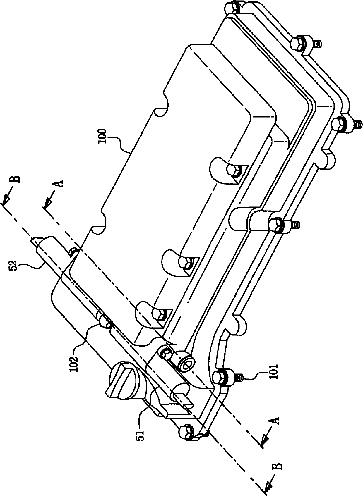
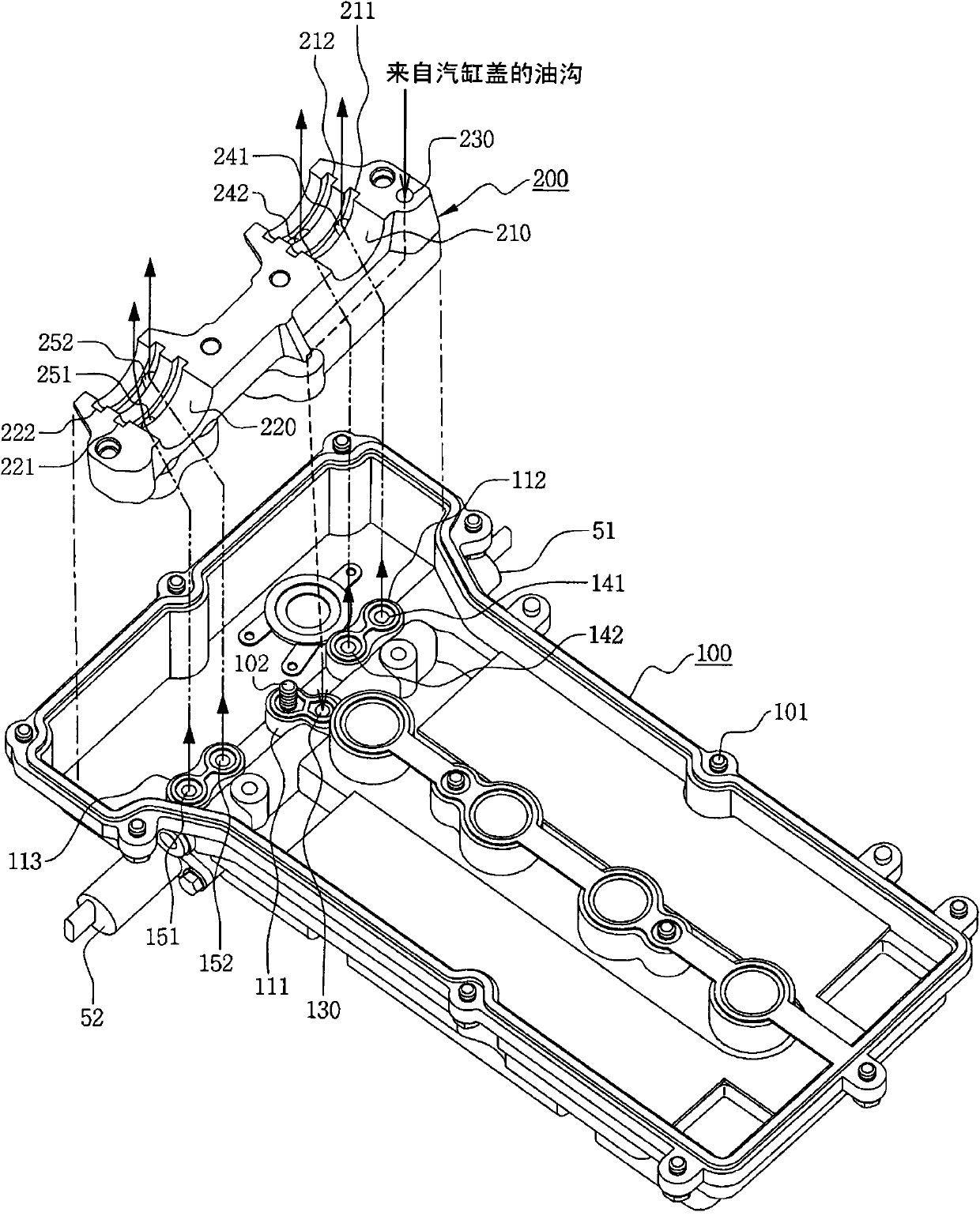
[0034] figure 1 and figure 2 The external appearance and internal appearance of a cylinder head cover assembly for a variable valve timing (VVT) system according to the present invention are shown.

[0035] Such as figure 1 As shown, the cylinder head cover assembly is configured such that the intake side oil pressure control valve 51 and the exhaust side oil pressure control valve 52 are disposed on opposite sides of the cylinder head cover 100 .

[0036] The intake side oil pressure control valve 51 controls the pressure and direction of oil to be supplied to the intake cam phaser, and the exhaust side oil pressure control valve 52 controls the pressure and direction of oil to b...


PUM


Abstract

The invention discloses a cylinder cover shield assembly related to and oil pressure control valve and used for a variable valve timing system (VVT system). The cylinder cover shield assembly comprises a cam cap fixedly installed on the upper surface of a cylinder cover and rotatably supporting the neck part of an air intake / outtake cam shaft, wherein a bearing receptacle on the air intake side is integrated with a bearing receptacle on the air outtake side; and a cylinder cover shield which is installed on the upper surface of the cylinder cover and can shield the air intake / outtake cam shaft and the cam cap, so that the inner surface of the cylinder cover shield contacts with the upper surface of the cam cap.

Description

technical field [0001] The present invention relates generally to a cylinder head cover assembly for a variable valve timing system associated with an oil control mechanism, and more particularly to a cylinder head cover assembly for a variable valve timing system in which, An oil pressure control valve for controlling oil to be supplied to a cam phaser is provided in the cylinder head cover, and an oil passage associated with the oil pressure control valve is made suitable for the cylinder head cover and the cam cover. Background technique [0002] In general, a variable valve timing system (hereinafter also referred to as a "VVT system") is a mechanism for, depending on the operating state of the engine (load, RPM (revolutions per minute), etc.), After setting the high-speed cam and the low-speed cam respectively, change the rotation phase of the intake cam or the intake and exhaust cams, change the phase and profile of the cam associated with the RPM, or change the valve ...

Claims


Application Information

Patent Timeline
Patent Type & Authority Applications(China)
IPC IPC(8): F01L1/34F02F7/00
CPCF01L1/344F01L2810/02F01M1/06F01M2001/064F02F1/24Y02T10/12
Inventor 金钟福
Owner GM GLOBAL TECH OPERATIONS LLC
Why Eureka
Eureka Blog
Learn More