Circuit structure and method for realizing USB interface functional verification test on the basis of FPGA module

A technology for USB interface and functional verification, applied in the field of USB interface, to achieve the effect of fast and convenient operation process, effective verification of USB interface, stable and reliable working performance

Active Publication Date: 2011-06-08
SPREADTRUM COMM (SHANGHAI) CO LTD
View PDF4 Cites 21 Cited by
  • Summary
  • Abstract
  • Description
  • Claims
  • Application Information

AI Technical Summary

Problems solved by technology

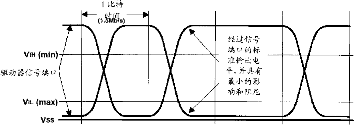
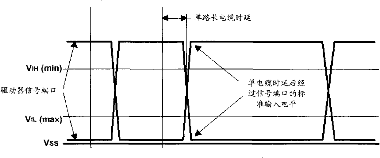
[0017] All hubs and high-speed functional device upstream ports (towards the host) must use high-speed drivers. Upstream hub ports can transmit data at both high and low speeds, but always use high and edge rates when signaling

Method used


Image

  • Circuit structure and method for realizing USB interface functional verification test on the basis of FPGA module
  • Circuit structure and method for realizing USB interface functional verification test on the basis of FPGA module
  • Circuit structure and method for realizing USB interface functional verification test on the basis of FPGA module

Examples


Embodiment Construction

[0080] In order to understand the technical content of the present invention more clearly, the following examples are given in detail.

[0081] see Image 6 As shown, this FPGA module realizes the circuit structure of the USB interface function verification test, wherein, the described circuit structure includes an FPGA module, an ARM chip, and the USB host control program is loaded in the described FPGA module, and the described FPGA module passes The LVDS signal interface is connected with the USB device to be tested, the FPGA module is connected with the ARM chip, and the ARM chip is connected with the test computer.

[0082] Wherein, the FPGA module is an FGPA chip, and the GPIO port and the PHOST port on the ARM chip are connected with the GPIO port of the FPGA chip; the ARM chip is connected to the test via a serial communication interface. The computer is connected.

[0083] The method for performing the USB interface function verification test using the above-mention...


PUM


Abstract

The invention relates to a circuit structure for realizing a universal serial bus (USB) interface functional verification test on the basis of a field programmable gate array (FPGA) module. The circuit module comprises an FPGA module and an advanced reduced instruction set computer (RISC) machine (ARM) chip, wherein a USB host control program is loaded in the FPGA module; the FPGA module is connected with USB equipment to be tested through a low voltage differential signaling (LVDS) signal interface and is also connected with the ARM chip; and the ARM chip is connected with a test computer. The invention also relates to a method for performing the USB interface functional verification test by using the circuit structure. By adopting the circuit structure and the method for realizing the USB interface functional verification test on the basis of the FPGA module, the test computer is communicated with the USB equipment to finish the processes of identification and enumeration with the USB equipment, and the ARM chip resolves a command sent by the test computer and controls a command which is sent to the test computer by the USB equipment, so that not only a USB interface can be verified more comprehensively, conveniently and effectively, but also the structure is simple and practical, the operation process is quick and convenient, the working performance is stable and reliable, and the application range is wide.

Description

technical field [0001] The invention relates to the field of USB interfaces of electronic equipment, in particular to the technical field of USB interfaces of functional chips of electronic equipment, and specifically refers to a circuit structure and a method for implementing a USB interface function verification test based on an FPGA module. Background technique [0002] USB is the abbreviation of Universal Serial Bus in English, and the Chinese meaning is "Universal Serial Bus". USB was jointly proposed by Intel, Compaq, IBM, Microsoft and other companies at the end of 1994. After years of development, the version has developed into version 2.0, which has become the standard expansion interface in computers. At present, the motherboard mainly adopts USB1.1 and USB2.0 (this article is mainly for USB1.1). Moreover, the USB interface can also realize dual-machine interconnection through a special USB connection line, and more interfaces can be expanded through the Hub. US...

Claims


Application Information

Patent Timeline
Patent Type & Authority Applications(China)
IPC IPC(8): G06F11/22
Inventor 张结华
Owner SPREADTRUM COMM (SHANGHAI) CO LTD
Why Eureka
Try Eureka