

Solar concentrating mirror
A technology of solar concentrating and reflecting mirrors, which is applied in the directions of solar thermal energy, solar collectors, and solar ray concentration, and can solve problems such as failure of solar concentrating mirrors and decline in concentrating efficiency
- Summary
- Abstract
- Description
- Claims
- Application Information
AI Technical Summary
Problems solved by technology
Method used
Image

Examples
example 1
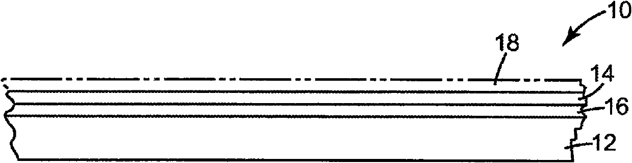
[0090] Using the same PEN and PMMA materials as in Comparative Example 1, a multilayer optical film was prepared with a birefringent layer made of PEN and a second polymer layer made of PMMA. PEN and PMMA were coextruded through a multilayer polymer melt manifold to produce a multilayer melt stream with 275 alternating birefringent and second polymer layers. In addition, a pair of non-optical layers, also composed of PEN, were coextruded as protective skin layers on either side of the optical layer stack. The multilayer coextruded melt stream was cast onto chilled rolls at 22 meters per minute, resulting in a multilayer cast web approximately 725 microns (29 mils) thick. The multilayer cast web was then heated in a tenter oven at 145°C for 10 seconds and then biaxially oriented to a draw ratio of 3.8 x 3.8. The oriented multilayer film was further heated to 225°C for 10 seconds to increase the crystallinity of the PEN layer. The reflectance of the multilayer visible mirror f...
example 2
[0092] Multilayer mirrors can be prepared with a birefringent layer made of PEN and a second polymer layer made of polyoxamide silicone (SPOX) from 3M Company, St. Pau, MN. PEN and SPOX layers were coextruded through a multilayer polymer melt manifold to produce a multilayer melt stream with 550 alternating first and second optical layers. In addition to the birefringent layer and the second polymer layer, a pair of non-optical layers also composed of PEN can be coextruded as protective skin layers on either side of the optical layer stack. The multilayer coextruded melt stream can be cast onto chilled rolls at 22 meters per minute, resulting in a multilayer cast web approximately 1400 microns (55 mils) thick. The multilayer cast web can then be heated in a tenter oven at 145°C for 10 seconds and then biaxially oriented to a draw ratio of 3.8 x 3.8. The oriented multilayer film can be further heated to 225°C for 10 seconds to increase the crystallinity of the PEN layer. The ...
example 3
[0094]Multilayer mirrors can be prepared with a birefringent layer made of PET and a second polymer layer made of SPOX (both from 3M Company). PEN and SPOX can be coextruded through a multilayer polymer melt manifold to produce a multilayer melt stream with 550 alternating birefringent and second polymer layers. Additionally, a pair of non-optical layers also composed of PEN can be coextruded as protective skin layers on either side of the optical layer stack. The multilayer coextruded melt stream can be cast onto chilled rolls at 22 meters per minute, resulting in a multilayer cast web approximately 1400 microns (55 mils) thick. The multilayer cast web can then be heated in a tenter oven at 95°C for 10 seconds and then biaxially oriented to a draw ratio of 3.8 x 3.8. The oriented multilayer film can be further heated to 225°C for 10 seconds to increase the crystallinity of the PEN layer. The reflectance of this multilayer visible mirror film can be measured with a LAMBDA 95...
PUM
 Abstract
Description
Claims
Application Information