Dust adhesion-resistant coated denitration catalytic sphere and preparation method thereof
A nitro-catalyzed ball and dust prevention technology, applied in chemical instruments and methods, separation methods, catalyst protection and other directions, can solve the problems of catalysts being easily blocked by fly ash, poisoning, etc., and achieve the effect of preventing adhesion and reducing costs.
- Summary
- Abstract
- Description
- Claims
- Application Information
AI Technical Summary
Problems solved by technology
Method used
Image

Examples
example 1
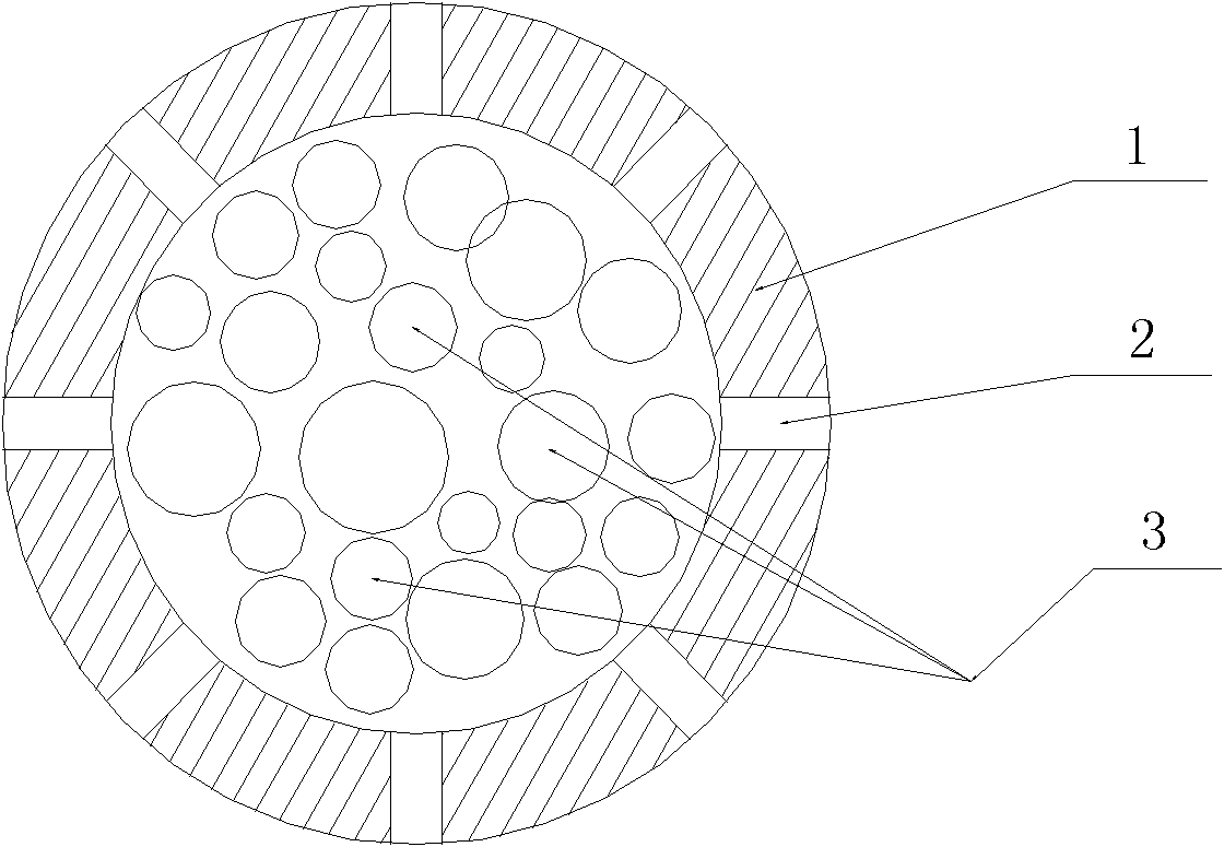
[0011] MnO with porous polytetrafluoroethylene as the shell and activated carbon as the carrier 2 -CeO 2 The base depinning catalyst is the filler. Use dispersed polytetrafluoroethylene to mold into a hemispherical shell body with an inner diameter of 8mm and a shell wall thickness of 1mm, and then sinter it at 350°C to form a hemispherical shell, and then use a puncher to punch a uniform hole diameter of 0.3 mm through hole. Then, 0.1 g of granular activated carbon with a particle size of 1 mm loaded with catalyst is loaded into the hemisphere, and finally the two hemispheres are formed into an integral sphere by thermocompression welding, thereby making a packaged denitration catalyst.
example 2
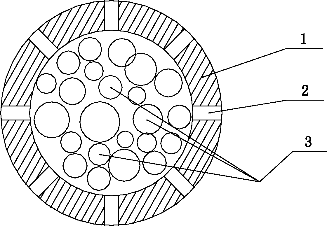
[0013] MnO with porous polytetrafluoroethylene as the shell and activated carbon as the carrier 1.7 -CeO 2 The base depinning catalyst is the filler. Use dispersed polytetrafluoroethylene to mold into a semi-spherical shell green body with an inner diameter of 10 mm and a shell wall thickness of 1.5 mm, and then sinter it at 350 ° C to form a semi-spherical shell, and then use a puncher to punch a uniform hole diameter of 0.5mm through hole. Then, 0.2 g of granular activated carbon with a particle size of 3 mm loaded with catalyst is loaded into the hemisphere, and finally the two hemispheres are formed into an integral sphere by thermocompression welding, thereby making a packaged denitration catalyst.
example 3
[0015] MnO with porous polytetrafluoroethylene as the shell and activated carbon as the carrier 1.5 -CeO 2 The base depinning catalyst is the filler. Use dispersed polytetrafluoroethylene to mold into a semi-spherical shell green body with an inner diameter of 10 mm and a shell wall thickness of 1.3 mm, and then sinter it at 350 ° C to form a semi-spherical shell, and then use a punching machine to punch a uniform hole diameter of 0.4mm through hole. Then, 0.15 g of granular activated carbon with a particle size of 2 mm loaded with catalyst is loaded into the hemisphere, and finally the two hemispheres are formed into an integral sphere by thermocompression welding, thereby making a packaged denitration catalyst.
PUM
| Property | Measurement | Unit |
|---|---|---|
| The inside diameter of | aaaaa | aaaaa |
| Graininess | aaaaa | aaaaa |
| The inside diameter of | aaaaa | aaaaa |
Abstract
Description
Claims
Application Information
 - R&D
- Intellectual Property
- Life Sciences
- Materials
- Tech Scout
- Unparalleled Data Quality
- Higher Quality Content
- 60% Fewer Hallucinations
Browse by: Latest US Patents, China's latest patents, Technical Efficacy Thesaurus, Application Domain, Technology Topic, Popular Technical Reports.
© 2025 PatSnap. All rights reserved.Legal|Privacy policy|Modern Slavery Act Transparency Statement|Sitemap|About US| Contact US: help@patsnap.com