Laser processing device and laser processing method using tool of the laser processing device

A technology of laser processing and processing procedures, applied in the direction of manufacturing tools, metal processing equipment, laser welding equipment, etc., can solve the problems of high cost, rough processing surface, and insufficient dimensional accuracy, etc., to achieve low cost and prolong life , The effect of preventing peeling or chipping

Inactive Publication Date: 2011-06-15
MITSUBISHI MATERIALS CORP
View PDF6 Cites 7 Cited by
  • Summary
  • Abstract
  • Description
  • Claims
  • Application Information

AI Technical Summary

Problems solved by technology

[0006] That is, in the laser processing technology of the above-mentioned conventional tools, since the usual general laser processing machine is used, not only the device itself, such as a large-scale motor capable of high-speed rotation, is large and the cost is high due to difficulty in control, etc., but also the processing machine When the stage or each axis starts to accelerate after operation or decelerates when stopped, the laser light is excessively irradiated, and the processed surface becomes rough, and sufficient dimensional accuracy cannot be obtained.

Method used


Image

  • Laser processing device and laser processing method using tool of the laser processing device
  • Laser processing device and laser processing method using tool of the laser processing device
  • Laser processing device and laser processing method using tool of the laser processing device

Examples


Embodiment 1

[0056] Next, refer to Figure 7 An example of actual machining of a tool using the laser machining apparatus of the above embodiment will be described.

[0057] in Figure 7 (a) shows an enlarged image of a Si wafer as an object to be processed, and the surface is processed into a linear surface using the laser processing apparatus of the above embodiment. In addition, in Figure 7 (b) shows an enlarged image of a surface processed in the same manner as conventional laser processing as a conventional example.

[0058] From this result, it can be seen that in the conventional laser processing, the processed shape (cross-section) of the object to be processed is processed to have a wider width than other regions by overlapping many processing marks after the start of processing. On the contrary, in the laser processing of this example, After the processing is started, processing marks are formed at the same intervals as in other areas, and processing is performed with uniform widths ...


PUM


Abstract

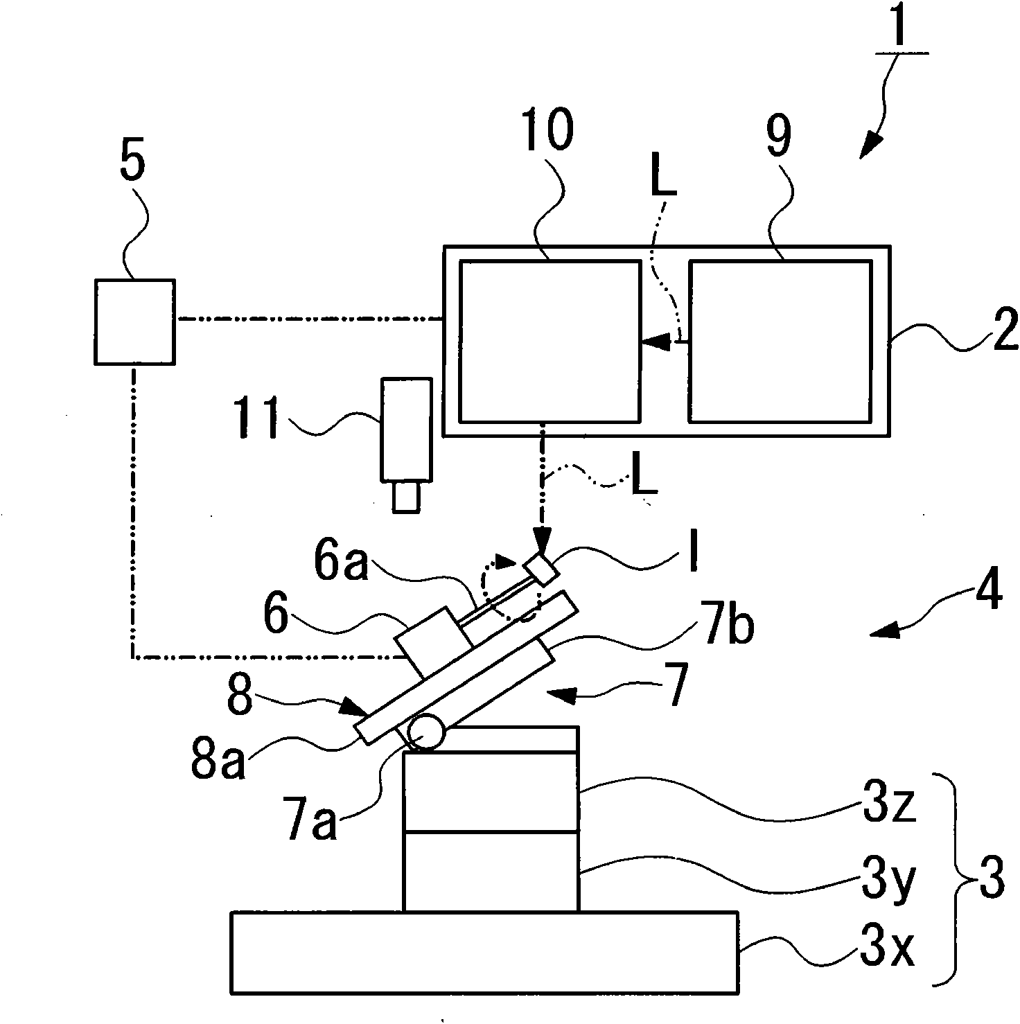
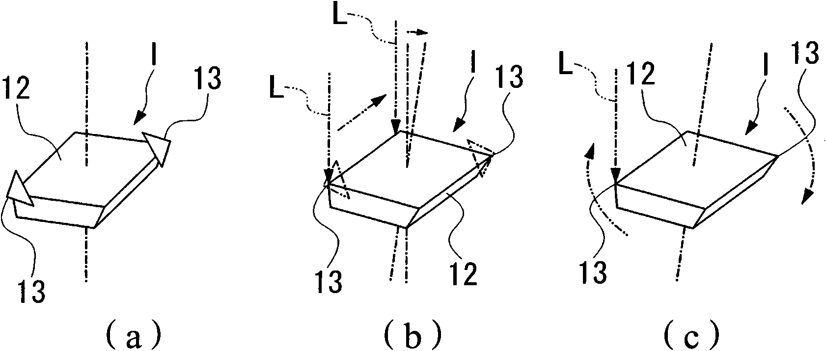
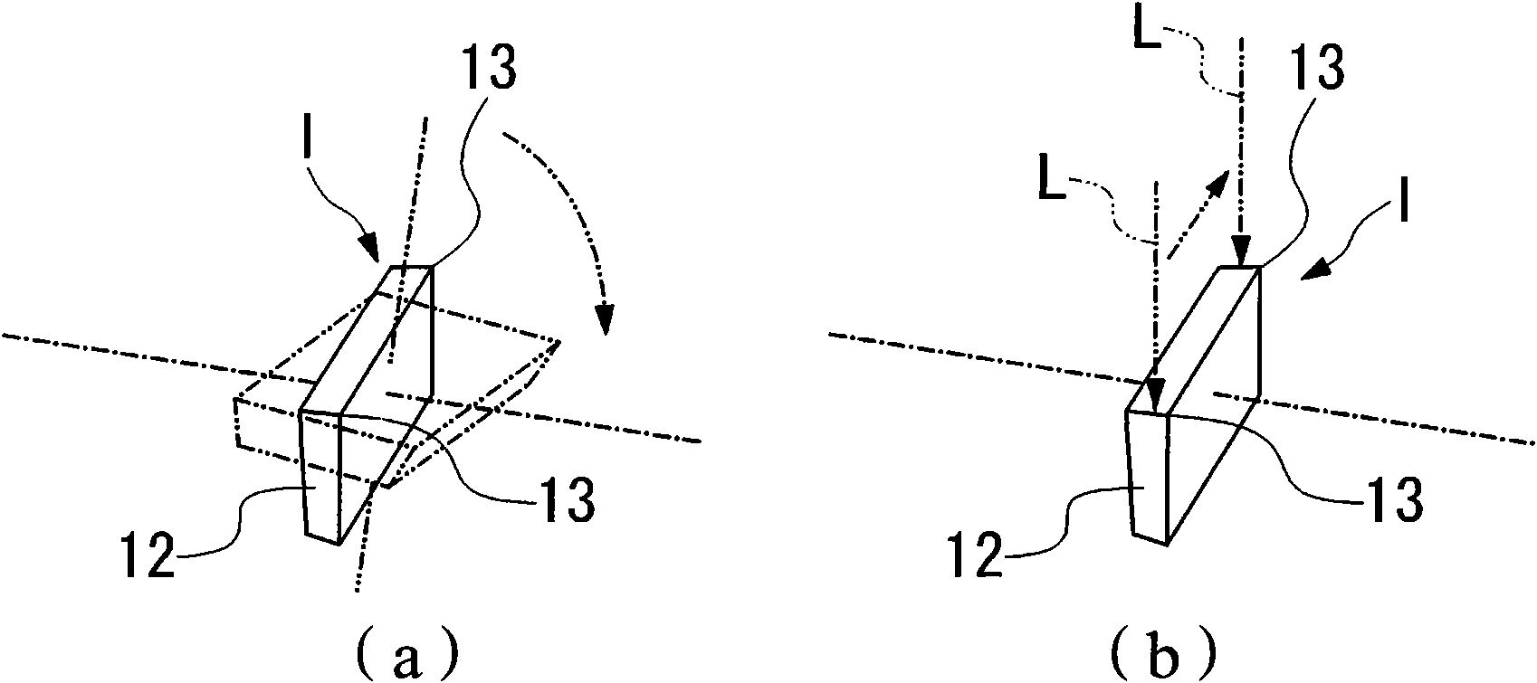
The invention provides a laser processing device and a laser processing method using a tool of the laser processing device, the laser processing device obtains high size precision via laser processing according to moving and rotating states of tools, etc. A device performing processing via irradiating laser light (L) to a waiting-to-be-processed image (I) is provided with: a laser illuminating mechanism (2) performing illuminating upon the waiting-to-be-processed image (I) via oscillating the laser light according to input trigger signals; a moving mechanism (4) capable of keeping the waiting-to-be-processed image at a rotary shaft (6a) to make the rotary shaft move or rotate, when a moving displacement amount of a moving objective table or a rotating displacement amount of the rotary shaft (6a) is outputted as coder signals; and a trigger signal generation circuit part (5) outputting trigger signals to the laser illuminating mechanism according to set counting amount while counting encoder signals.

Description

Technical field [0001] The present invention relates to a laser processing device suitable for processing cBN tools and the like and a laser processing method of a tool using the laser processing device. Background technique [0002] Generally, cBN tools using cBN (cubic boron nitride) sintered bodies as ultra-high pressure sintered bodies are processed into a sheet shape by electric discharge machining of the cBN sintered body, and then brazed to the tool base material by a precision grinding device Further shape it as a cutting blade tool. When a very small blade tool is fixed to a precision grinding device and polished, since the tool itself is small, there are problems such as a drop in dimensional accuracy due to peeling from the brazed part, chipping, or looseness when contacting the grinding wheel. [0003] Conventionally, as a method of processing tools other than a precision polishing device, for example, Patent Document 1 proposes a method of forming recesses in the shap...

Claims


Application Information

Patent Timeline
Patent Type & Authority Applications(China)
IPC IPC(8): B23K26/00B23K26/36B23K26/08B23K26/04B23P15/28
Inventor 高桥正训日向野哲
Owner MITSUBISHI MATERIALS CORP
Why Eureka
Try Eureka