Supercharge Your Innovation With Domain-Expert AI Agents!

Air blower for a fuel cell vehicle

A technology for fuel cell vehicles and blowers, applied to liquid fuel engines, parts of pumping devices for elastic fluids, mechanical equipment, etc., can solve the problem of poor cooling efficiency and durability, difficulty in cooling motors and control boxes, Reduce the size and weight of fuel cell vehicles to achieve the effect of improving durability and cooling efficiency

Inactive Publication Date: 2011-06-15
HANON SYST
View PDF7 Cites 9 Cited by
  • Summary
  • Abstract
  • Description
  • Claims
  • Application Information

AI Technical Summary

Problems solved by technology

Therefore, it is difficult to reduce the volume and weight of fuel cell vehicles
[0006] In addition, according to the prior art, it is difficult to cool the motor and the control box sufficiently, so cooling efficiency and durability deteriorate

Method used


Image

  • Air blower for a fuel cell vehicle
  • Air blower for a fuel cell vehicle
  • Air blower for a fuel cell vehicle

Examples


Embodiment Construction

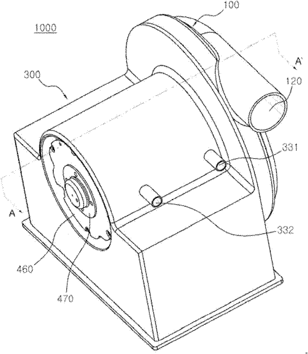
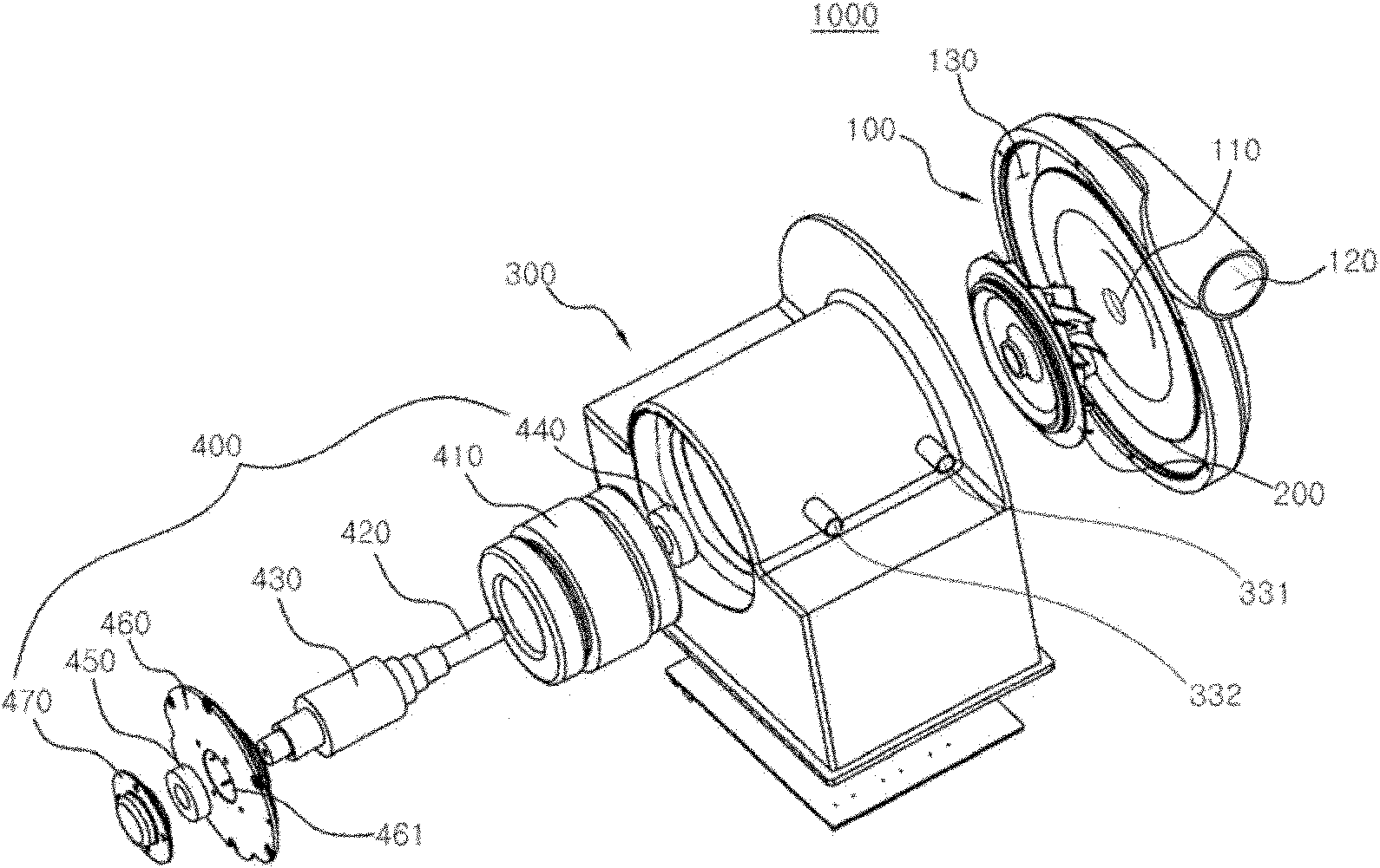
[0060] Hereinafter, a blower fan 1000 for a fuel cell vehicle according to the present invention will be described in detail with reference to the accompanying drawings.

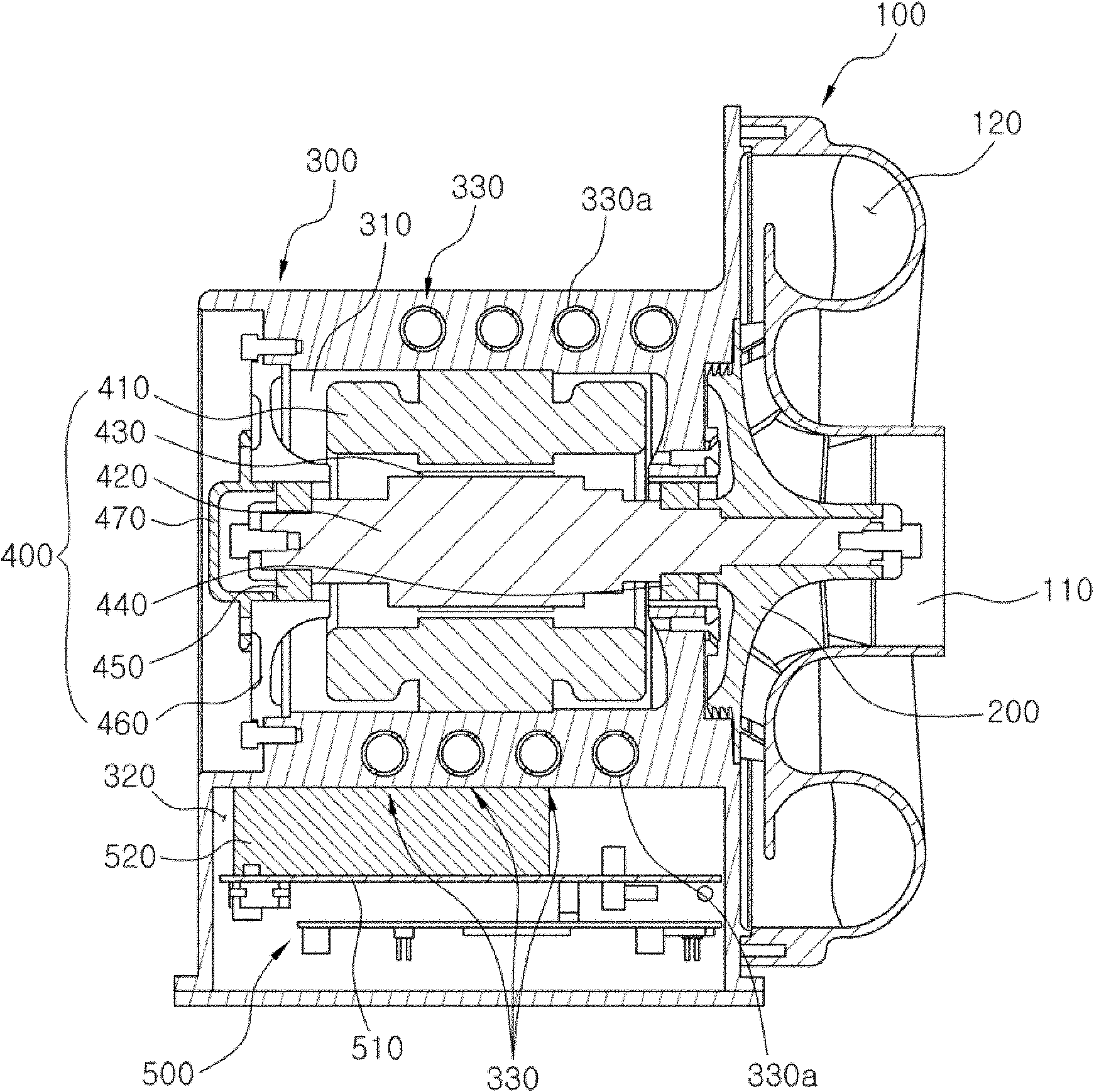
[0061] The blower 1000 for a fuel cell vehicle according to the present invention is configured to include a scroll housing 100 , an impeller 200 , a motor housing 300 and a motor 400 , wherein the motor housing 300 is provided with a cooling water passage 330 .

[0062] An air inlet 110 for air to enter is provided in the axial direction of the volute housing 100 , and an air outlet 120 for air to be discharged is provided in the radial direction of the volute housing. An air passage 130 connected to the air inlet 110 and the air outlet 120 to move air is formed along the inner peripheral surface of the scroll housing 100 .

[0063]The impeller 200 is disposed in the scroll housing 100 to compress the air entering through the air inlet 110 . Most of the air entering through the air inlet 110 is compressed ...


PUM


Abstract

Provided is an air blower for a fuel cell vehicle, and in particular, an air blower for a fuel cell vehicle having a cooling water passage formed in a motor case and an air flowing groove to increase cooling efficiency and reduce a shaft load to improve durability.

Description

technical field [0001] The present invention relates to a blower for a fuel cell vehicle capable of improving cooling efficiency and durability. Background technique [0002] Generally, a fuel cell vehicle is driven by electric energy continuously generated by an electrochemical reaction such as when hydrogen supplied from a fuel supply device and oxygen in air supplied from an air supply device are supplied to a humidifier The reverse reaction of the electrolysis of the resulting water. [0003] A fuel cell vehicle is configured to include: a fuel cell stack for generating electricity; a humidifier for humidifying and supplying fuel and air in the fuel cell stack; a fuel supply device for supplying hydrogen to the humidifier; an air supply device for supplying air to the humidifier; and a cooling module for cooling the fuel cell stack. [0004] The air supply device is configured to include: an air cleaner for filtering impurities contained in the air; a blower that compr...

Claims


Application Information

Patent Timeline
Patent Type & Authority Applications(China)
IPC IPC(8): F04D25/08F04D29/42F04D29/58
CPCF04D25/082F04D29/584F04D17/10F04D25/06F04D29/5806F04D29/5813
Inventor 赵庆锡崔淳浩梁铉燮林车孺
Owner HANON SYST
Features
  • R&D
  • Intellectual Property
  • Life Sciences
  • Materials
  • Tech Scout
  • Unparalleled Data Quality
  • Higher Quality Content
  • 60% Fewer Hallucinations
Learn More