Optical path structure of time-division-multiplexing optical fiber hydrophone array and modulation and demodulation method thereof

A fiber optic hydrophone and time-division multiplexing technology, applied in optical demodulation, time-division multiplexing systems, optical fiber transmission, etc., can solve the problems of increased dependence, increased signal demodulation, and higher costs

Active Publication Date: 2011-06-15
INST OF ACOUSTICS CHINESE ACAD OF SCI
View PDF4 Cites 54 Cited by
  • Summary
  • Abstract
  • Description
  • Claims
  • Application Information

AI Technical Summary

Problems solved by technology

[0032] 1. The PGC internal modulation is used, that is, the phase modulation is completed by directly modulating the frequency of the light source, which can ensure the full photonization of the wet end, but the cost of frequency-tunable lasers is very high
[0033] 2. Due to its inherent working mechanism, internal modulation requires a certain optical path difference between the two paths of light participating in the interference, which is very unfavorable for reducing noise
This necessary optical path difference also corresponds to the modulation capability of the laser. If the light source modulation capability is not strong enough, the necessary optical path difference must be large, so that the coherence (or monochromaticity) of the system to the light source The dependence of , thus, will inevitably increase the influence of the frequency noise of the laser
If you try to control the necessary path difference to be very small to meet the needs of noise reduction, it will inevitably require a strong modulation ability of the light source, so it is obvious that the cost will increase. For manufacturers, whether the laser can meet the technical requirements is also a big problem. big challenge
[0034] 3. The optical interference is completed underwater, and then the interference signal is transmitted to the dry end through the optical fiber. The power of the light transmitted in the long-distance transmission line changes, which also easily increases the instability of signal demodulation

Method used


Image

  • Optical path structure of time-division-multiplexing optical fiber hydrophone array and modulation and demodulation method thereof
  • Optical path structure of time-division-multiplexing optical fiber hydrophone array and modulation and demodulation method thereof
  • Optical path structure of time-division-multiplexing optical fiber hydrophone array and modulation and demodulation method thereof

Examples


Embodiment Construction

[0084] The present invention will be further described below in conjunction with the accompanying drawings and specific embodiments.

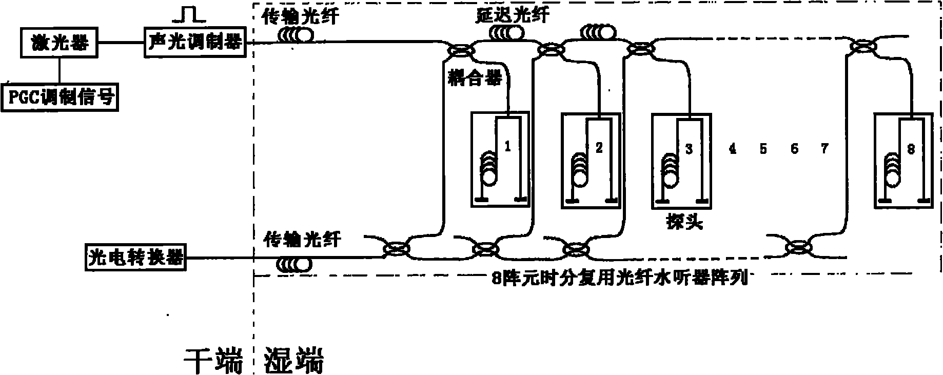
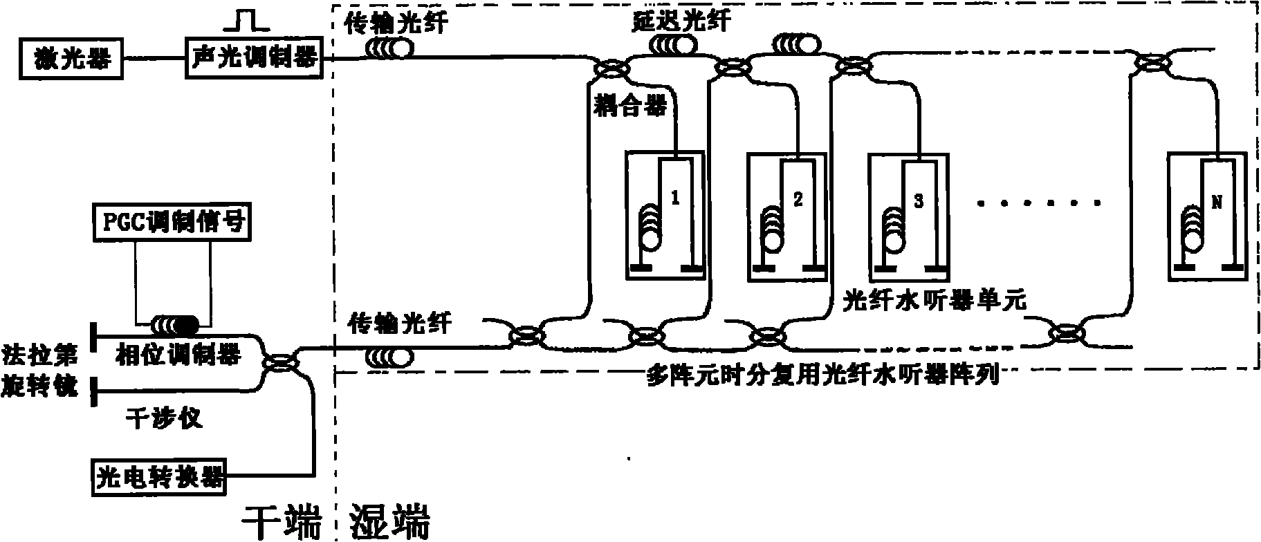
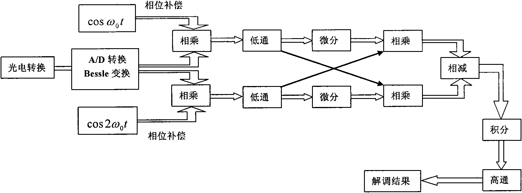
[0085] like figure 1 and 2 As shown, the present invention proposes a phase modulation and demodulation method generated outside the time-division multiplexing optical fiber hydrophone array. The technical problem to be solved is: adopting a new time-division multiplexing optical path structure design to make light interfere at the dry end, and The dry end realizes the PGC external modulation to ensure the full opticalization of the wet end, solves the asynchrony of the phase generation of the external modulation of the time-division multiplexing fiber optic hydrophone array, and realizes the correct demodulation of the signal. Taking the 8-element array as an example, the description is as follows:

[0086] ① The light emitted by the laser is output to the acousto-optic modulator through an optical fiber;

[0087] ②The acousto-optic modulat...


PUM


Abstract

The invention relates to an optical path structure of a time-division-multiplexing optical fiber hydrophone array and a modulation and demodulation method thereof. The time-division-multiplexing optical fiber hydrophone array comprises a laser and an acousto-optical modulator at the input end thereof, wherein the acousto-optical modulator is used for modulating a light wave, sent out by the laserthrough an optical fiber, into a light interrogation pulse and then inputting the light interrogation pulse to the time-division-multiplexing optical fiber hydrophone array for interrogation; the optical path difference between two arms of an optical fiber hydrophone unit is larger than the persistence length of the light interrogation pulse, and when the light pulse is reflected by Faraday rotary mirrors at two arm ends and then returns to a coupler, the reflected pulses at two arms are free from interference, but respectively reach a dry end through water in order; the time-division-multiplexing optical fiber hydrophone array comprises an interferometer and a phase modulator at the output end thereof; and the light interrogation pulse is reflected by the Faraday rotary mirrors at two arm ends and then returns to the coupler, then enters the interferometer for interference, is subjected to PGC (Phase Generation Carrier) external modulation, and is finally photoelectrically converted to an electric signal.

Description

technical field [0001] The invention relates to a modulation and demodulation method of a time-division multiplexing optical fiber hydrophone array, more specifically, an optical path structure and a modulation and demodulation method of a time-division multiplexing optical fiber hydrophone array. Background technique [0002] Time division multiplexing is one of the most common ways of multiplexing fiber optic hydrophone arrays. The current time-division multiplexing method is to complete the interference of light underwater, and then the interference signal is transmitted to the dry end through the optical fiber (the underwater part is called the wet end in the field of underwater acoustics, and the onshore part is called the dry end). The power of the light transmitted in the transmission line is variable, which also easily increases the instability factor of signal demodulation. [0003] Phase Generated Carrier (PGC, Phase Generated Carrier) demodulation is one of the m...

Claims


Application Information

Patent Timeline
IPC IPC(8): G01H9/00G02F2/00H04J3/00H04B10/12H04B10/25
Inventor 黄晓砥陈德胜王海斌江磊
Owner INST OF ACOUSTICS CHINESE ACAD OF SCI
Why Eureka
Try Eureka