Gradient system time delay correction method for fast spin echo pulse sequence

A technology of system delay and spin echo, which is applied in the direction of measuring devices, measuring magnetic variables, instruments, etc., can solve the problems of unequal delay of gradient system, inability to take into account delay, delay correction of FSE image artifacts, etc.

Inactive Publication Date: 2011-06-15
EAST CHINA NORMAL UNIVERSITY +1
View PDF3 Cites 27 Cited by
  • Summary
  • Abstract
  • Description
  • Claims
  • Application Information

AI Technical Summary

Problems solved by technology

[0005] Question 1: In the magnetic resonance system, in the three gradient directions of xyz, the number of pre-emphasis channels in each direction is 3 to 5
The time constants of these channels need to be set according to the characteristics of the eddy current. Due to the small number of channels, it is difficult to accurately correct the delay of the gradient system while compensating for the eddy current
[0006] Question 2: The gradient system delay is determined by the gradient system
However, the delay of the gradient system has not changed. At this time, the delay of the gradient system cannot be corrected flexibly and accurately.
[0007

Method used


Image

  • Gradient system time delay correction method for fast spin echo pulse sequence
  • Gradient system time delay correction method for fast spin echo pulse sequence

Examples


Embodiment Construction

[0024] The features of the present invention and other related features will be further described below through embodiments in conjunction with the accompanying drawings.

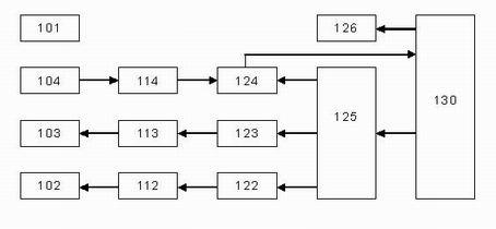
[0025] figure 1 It is a block diagram of the MRI system according to the present invention. In an MRI system, the magnet 101 has a cavity for placing the sample. A gradient coil 102 is placed around the cavity for generating gradient magnetic fields in the slice selection direction, the phase encoding direction and the reading direction, so as to spatially locate the sample. A radio frequency transmitting coil 103 and a radio frequency receiving coil 104 are placed around the cavity, the transmitting coil is used for transmitting radio frequency pulses to excite the magnetization vector of the sample, and the receiving coil is used for receiving the magnetization vector precession signal. The gradient coil 102 is connected to the gradient power amplifier 112 , and the transmitting coil 103 and the receivi...


PUM


Abstract

The invention provides a gradient system time delay correction method for a fast spin echo pulse sequence. In the method, a gradient system time delay is corrected by correcting a gradient pulse, and an amplitude synthetic matrix for correcting the gradient pulse is calculated by using the normalized gradient system time delay. By the method, the influence of the gradient system time delay on thefast spin echo pulse sequence is overcome, and the hardware cost and the system complexity of a magnetic resonance imaging system are not increased; and even if the gradient system time delays in x, y and z directions are unequal, the power of a gradient power amplifier is not enough to provide overshooting impulse with larger amplitude in a gradient waveform. By the method, the gradient system time delay can still be corrected so as to enhance the image quality of a sagittal plane, a coronal plane, a cross section and various diagonal planes in a fast spin echo image.

Description

technical field [0001] The present invention relates to a magnetic resonance imaging (MRI) method, in particular, to a pulse sequence correction method adopted in order to reduce the image artifacts caused by the gradient system delay in the magnetic resonance fast spin echo (FSE) imaging technology. Background technique [0002] Magnetic resonance imaging (MRI) technology has become a very useful tool in medical diagnosis. Usually, in a magnetic resonance imaging system, when the sample (patient) under test is placed in a static magnetic field B 0 (B 0 When equilibrium is reached in the direction defined as the z-axis direction of the physical coordinate system, the nuclei (nuclear spins) in the sample are affected by B 0 polarization to produce a macroscopic magnetization vector M 0 . M 0 It is rotated into the horizontal plane (xy plane) under the excitation of the radio frequency pulse, and then precesses around the z axis. A receiver coil is placed around the samp...

Claims


Application Information

Patent Timeline
IPC IPC(8): G01R33/561
Inventor 宁瑞鹏杨光李鲠颖
Owner EAST CHINA NORMAL UNIVERSITY
Why Eureka
Try Eureka