An optical transmission projection stereoscopic helmet-mounted display

A helmet display and optical transmission technology, which is applied in optics, optical components, instruments, etc., can solve the problems of unclear imaging, difficult to realize optical transmission large field of view helmet display, large display physical structure collision, etc.

Active Publication Date: 2016-04-13
BEIJING NEDPLUSAR DISPLAY TECH CO LTD
View PDF6 Cites 0 Cited by
  • Summary
  • Abstract
  • Description
  • Claims
  • Application Information

AI Technical Summary

Problems solved by technology

[0015] In order to solve the problem that the traditional rotationally symmetric optical system is difficult to realize the optical transmissive large field of view head-mounted display, in order to effectively solve the collision problem of the physical structure of the large display, in order to solve the problem that the distance between the projection system and the reflective screen in the existing projection type head-mounted display is too large The problem of unclear imaging in recent times

Method used


Image

  • An optical transmission projection stereoscopic helmet-mounted display
  • An optical transmission projection stereoscopic helmet-mounted display
  • An optical transmission projection stereoscopic helmet-mounted display

Examples


no. 1 example

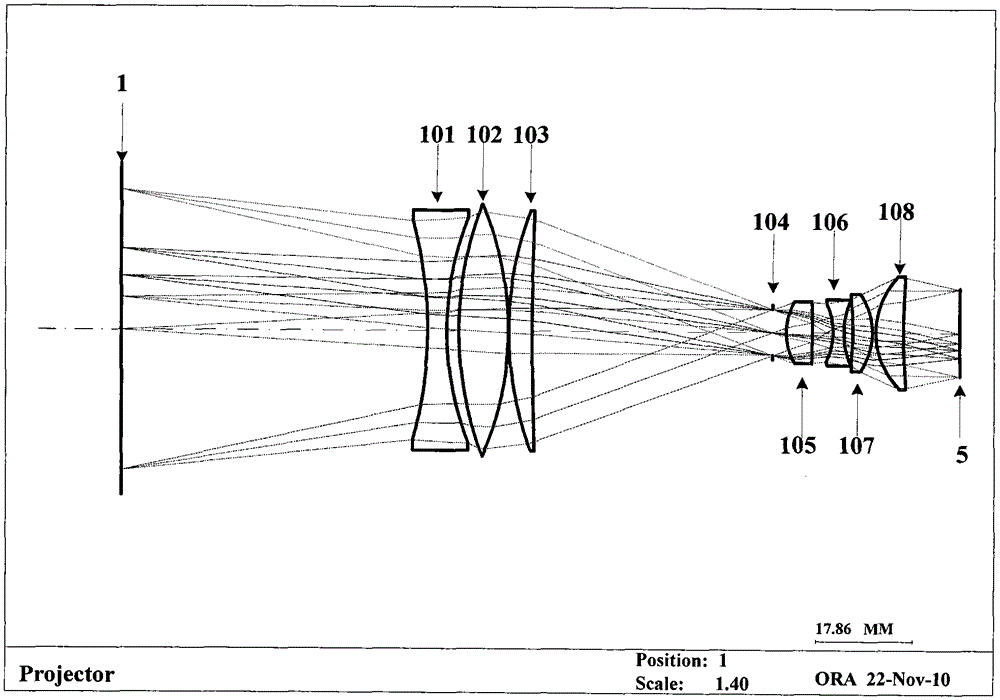
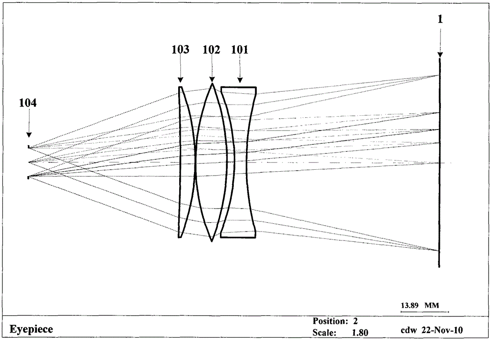
[0045] figure 2 It shows a schematic structural diagram of the close-range micro-projection optical system of the projection-type head-mounted display device according to the first embodiment of the present invention; image 3 A schematic diagram of the eyepiece optical system of the projection head-mounted display device according to the first embodiment of the present invention is shown. Such as figure 2 As shown, the short-distance micro-projection system of the projection-type helmet display device according to the first embodiment of the present invention is composed of an eyepiece group and a rear projection lens. For the convenience of describing the projection optical system is carried out from the display screen to the direction of the micro-display. From left to right is 1, the scattering projection screen; 101 is a biconcave lens with negative dioptric power, 102 is a lens with positive dioptric power, and 103 is a lens with positive dioptric power; 104 is the d...

no. 2 example

[0055] image 3 It shows a schematic structural diagram of the close-range micro-projection optical system of the projection-type head-mounted display device according to the first embodiment of the present invention; Figure 4 A schematic diagram of the eyepiece optical system of the projection head-mounted display device according to the first embodiment of the present invention is shown. Such as image 3 As shown, the short-distance micro-projection system of the projection-type helmet display device according to the first embodiment of the present invention is composed of an eyepiece group and a rear projection lens. For the convenience of describing the projection optical system is carried out from the display screen to the direction of the micro-display. From left to right is 1 scattering projection screen; 201 is a biconcave lens with negative dioptric power, 202 is a lens with positive dioptric power, and 203 is a lens with positive dioptric power; 204 is the diaphra...

no. 3 example

[0064] Figure 6 It shows a schematic structural diagram of the close-range micro-projection optical system of the projection-type head-mounted display device according to the first embodiment of the present invention; Figure 7 A schematic diagram of the eyepiece optical system of the projection head-mounted display device according to the first embodiment of the present invention is shown. Such as Figure 6 As shown, the short-distance micro-projection system of the projection-type helmet display device according to the first embodiment of the present invention is composed of an eyepiece group and a rear projection lens. For the convenience of describing the projection optical system is carried out from the display screen to the direction of the micro-display. From left to right is 1, the scattering projection screen; 301 is a biconvex lens with positive dioptric power; 302 is the stop surface of the close-range micro-projection optical system; 303 is a lens with positive ...


PUM


Abstract

The invention proposes a projection type optical transmission type helmet display system. It consists of a close-range micro-projection system, a beam splitter and a diffuser screen. The structure of the short-distance micro-projection system is rather special. It consists of an eyepiece and a projection objective. The lens group 2 acts as an eyepiece and is also a part of the close-range micro-projection system. This ensures that the image projected by the projection system onto the screen is a clear, real image. The image formed on the scattering screen is magnified through the eyepiece, reflected by the half mirror and entered into the human eye, and at the same time the image is formed in a far place.

Description

technical field [0001] The invention relates to an optical transmission projection stereoscopic helmet display optical system, which is especially suitable for virtual reality or augmented reality systems. Background technique [0002] Sir Charles Wheatstone, a British inventor, invented the first 3D stereoscopic screen viewer based on the principle of parallax in 1838, but at that time photos had not yet been invented, and pictures drawn by hand were used. In 1859, Oliver Wendel Holmes improved the patent of Joseph Bates and invented the hand-held pocket screen viewer, whose principle has been popular until today. Since the observed image of the stereoscopic screen viewer is a picture for a long time, the stereoscopic image cannot be played continuously, and its use has been limited to a certain extent. The stereo vision of the helmet display technology is also based on this principle. [0003] The advantage of picture display is that its size can be made relatively large...

Claims


Application Information

Patent Timeline
Patent Type & Authority Patents(China)
IPC IPC(8): G02B27/01G02B27/22G02B7/02
Inventor 程德文王涌天翁冬冬刘越
Owner BEIJING NEDPLUSAR DISPLAY TECH CO LTD
Why Eureka
Try Eureka