Turbine blade

一种叶片、涡轮的技术,应用在燃气轮机领域,能够解决燃气轮机气体温度下降、燃气轮机热效率降低等问题,达到提高热效率、提高性能、减少总体冷却空气量的效果

Inactive Publication Date: 2011-06-15
MITSUBISHI HEAVY IND LTD
View PDF4 Cites 3 Cited by
  • Summary
  • Abstract
  • Description
  • Claims
  • Application Information

AI Technical Summary

Problems solved by technology

As a result, low-temperature cooling air is blown out from the film cooling holes, the gas temperature of the gas turbine decreases, and the thermal efficiency of the gas turbine may decrease.

Method used


Image

  • Turbine blade
  • Turbine blade
  • Turbine blade

Examples


Embodiment Construction

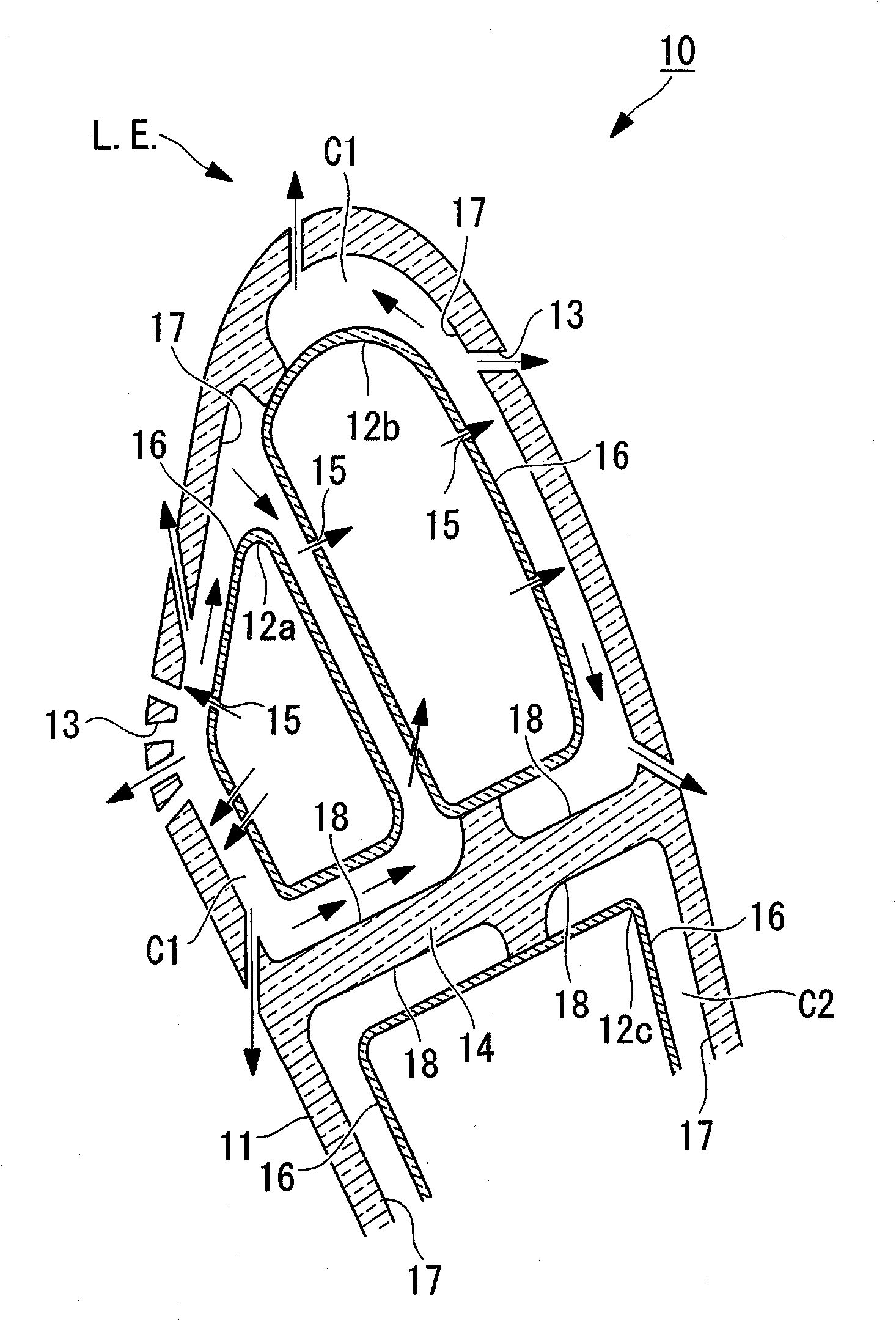
[0027] Below, refer to figure 1 and figure 2 One embodiment of the turbine blade according to the present invention will be described.

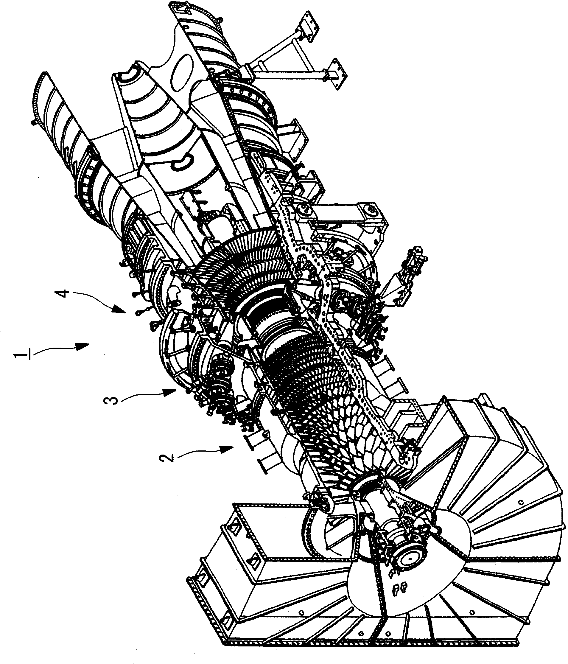
[0028] figure 1 It is a schematic perspective view showing a gas turbine 1 provided with a turbine blade 10 according to the present invention, showing a state where the upper half of the wheel house is removed, figure 2 It is a cross-sectional view of a main part of the turbine blade 10 according to the present embodiment, when the substantially central portion is cut along a plane substantially perpendicular to the axis in the direction in which it is erected.

[0029] Such as figure 1 As shown, the gas turbine 1 mainly includes: a compression part 2 that compresses combustion air, a combustion part 3 that injects fuel into the high-pressure air sent from the compression part 2 and burns it to generate high-temperature combustion gas, and is located in the combustion part. The turbine part 4 is driven by the combustion gas blown out ...


PUM


Abstract

The invention provides a turbine blade which can reduce an amount of cooling air (cooling medium), and in addition, prevent cooling air at a low temperature from being blown out from a film cooling hole. After part of the cooling medium which has impinge-cooled an inner peripheral surface (17) located on a front of a blade body (11) further impinge-cools the inner peripheral surface (17) located on a back of the blade body (11), it is blown out from the film cooling hole (13) located on the back of the blade body (11).

Description

technical field [0001] The present invention relates to a gas turbine, and more specifically relates to turbine blades (stationary blades, moving blades) of the gas turbine. Background technique [0002] As a turbine blade (for example, a second-stage stator blade) in a turbine section of a gas turbine, a turbine blade disclosed in Patent Document 1, for example, is known. [0003] Patent Document 1 Japanese Patent Application Laid-Open No. 3-253701 [0004] However, in the turbine blade disclosed in Patent Document 1, in order to efficiently cool the inner wall surface (inner peripheral surface) of the blade body, it is necessary to locate the turbulent flow holes as close as possible to the inner wall surface of the blade body. way to configure the wall of the insert. As a result, the cross-sectional area of ​​the flow path of the insert inevitably increases, the amount of cooling air increases, and the performance of the gas turbine decreases. [0005] In addition, the...

Claims


Application Information

Patent Timeline
Patent Type & Authority Applications(China)
IPC IPC(8): F01D9/02F01D5/18
CPCF05D2260/201F01D5/189F05B2260/201F05D2260/202F05B2260/202
Inventor 羽田哲桥本朋子由里雅则桑原正光
Owner MITSUBISHI HEAVY IND LTD
Why Eureka
Try Eureka