Multi-point forming device for plate

A multi-point forming and plate technology, applied in the field of sheet metal stamping, can solve the problems of high device cost, high device cost, difficult to meet the forming of complex parts, etc., to achieve convenient composition and adjustment, simple adjustment method, and restrain the sheet metal from rising. wrinkle effect

Active Publication Date: 2011-06-22
HARBIN INST OF TECH AT WEIHAI
View PDF18 Cites 62 Cited by
  • Summary
  • Abstract
  • Description
  • Claims
  • Application Information

AI Technical Summary

Problems solved by technology

But there are also significant deficiencies: the degree of deformation of rubber is limited, and it is difficult to meet the forming of complex parts with large deformation; both viscous medium forming and liquid-filled deep drawing need to control the pressure and flow of the force transmission medium, which needs to be controlled on the mold. Additional pressure control systems and mechanisms are added, which increases the complexity of the forming device and the control requirements for actual production
CN1994611A adopts an elastic cushion, and proposes to sandwich the sheet in a certain elastic cushion for forming in multi-point forming, and rely on the deformation of the elastic cushion to impose normal constraints on the sheet, but in fact, wrinkling is more It appears in the initial stage of forming, and the elastic cushion layer only works when the upper and lower molds are basically pressed together or at the end of forming, and it cannot completely solve the problem of forming wrinkles
CN2460239Y proposes a device that does not adjust the position of the indenter in advance, but simultaneously adjusts the displacement and speed of all punches during forming to realize loading and deformation. However, the structure is complicated, the control is difficult, and the cost of the device is high: this device needs to install a set of specially manufactured hydraulic valves and hydraulic cylinders driven by stepping motors or servo motors on each indenter. The rotation of the motor is used to control the displacement of the hydraulic cylinder. Due to the large number of pressure heads (often reaching hundreds or more), it is actually necessary to realize the simultaneous position detection and real-time speed and displacement control of hundreds or even hundreds of pressure heads. High requirements on the control system also lead to high cost of the device
CN1864884A proposes a combination of multi-point structure and viscous medium control on the upper half mold, and a forming device using viscous medium on the lower half mold. It also adopts the same method of not adjusting the pressure head in advance, but synchronously controlling the rotation of the stepping motor during the forming process. And control the flow and pressure of the viscous medium at the same time to realize the normal constraint on the sheet during the sheet forming process, but the disadvantages of complex structure, difficult control, and high device cost still exist: this device also needs to be installed on each indenter A set of high-power stepping motors can drive the rotating device to drive the pressing head down to deform the sheet metal during the forming process, and each stepping motor needs to be controlled in real time during the deformation process to achieve the final forming purpose , at the same time, multiple electro-hydraulic proportional relief valves are required to control the pressure of the viscous medium
Moreover, since the viscous medium itself is a fluid, when the sheet is hard or thick, a relatively high pressure is required to ensure that the sheet is formed accurately, and it is difficult for ordinary proportional valves to meet the requirements.

Method used


Image

  • Multi-point forming device for plate
  • Multi-point forming device for plate
  • Multi-point forming device for plate

Examples


Embodiment Construction

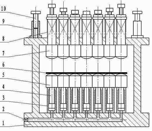
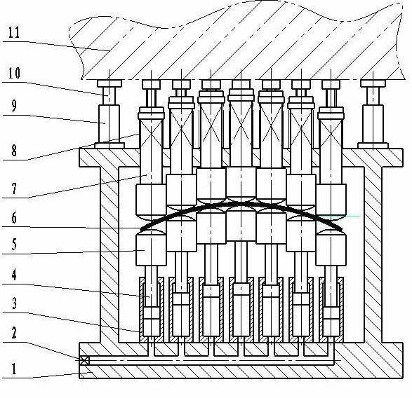
[0021] From figure 1 , figure 2 As can be seen in the figure, a plate multi-point forming device includes a formwork 1, a number of upper pressure head pressing units installed on the upper plate of the formwork 1, and a number of lower indenter support units installed on the lower plate of the formwork. The upper pressing head pressurizing unit is composed of an upper pressing head 7, a spring 8 and a stroke adjustment assembly. The upper pressing head 7 is installed in the positioning hole of the upper plate of the formwork 1 and can move up and down along the axis of the hole. The spring 8 is installed Between the upper ram 7 and the upper plate of the mold frame 1, it is used for the return stroke of the upper ram press unit after the pressing is completed; the lower ram support unit is composed of the lower ram 5, the plunger 4 and the hydraulic cylinder 3, The hydraulic cylinder 3 is fixed on the lower plate of the formwork 1, and the plunger 4 is connected with the lo...


PUM


Abstract

The invention relates to a multi-point forming device for a plate. The device comprises a die carrier, a plurality of upper pressure head pressurizing units and a plurality of lower pressure head supporting units, wherein the plurality of upper pressure head pressurizing units are arranged on an upper flat plate of the die carrier; the plurality of lower pressure head supporting units are arranged on a lower flat plate of the die carrier; each upper pressure head pressurizing unit consists of an upper pressure head, a spring and a travel adjusting component; an upper pressure head is arrangedin a positioning hole on the upper flat plate of the die carrier, and can move up and down along the axis of the hole; the spring is arranged between the upper pressure head and the upper flat plate of the die carrier; each lower pressure head supporting unit consists of a lower pressure head, a plunger and a hydraulic cylinder; the hydraulic cylinder is fixed on the lower flat plate of the die carrier; and the plunger is connected with the lower pressure head. A forming curved surface can be formed optionally and is easy and convenient to adjust. Any element is not required to be adjusted inreal time in a forming process, and stable and uniform normal pressure always acts on the plate, so that effective normal constraint is formed and the plate can be effectively prevented from wrinkling. The device has a reasonable structure, is easy to operate, works reliably, and is an ideal multi-point forming device for the plate.

Description

technical field [0001] The invention relates to the technical field of plate stamping, in particular to a plate multi-point forming device. It is suitable for the forming of curved sheet parts. Background technique [0002] Various types of plate forming parts are widely used in industries such as automobiles, aerospace, ships, machinery, and pressure vessels. Traditional plate forming is generally realized by die stamping, that is, using a stamping die to press the plate on a press to obtain the required parts. Shape, with the development of modern technology, higher and higher requirements are put forward for the stamping precision and product quality of sheet metal forming parts, and the shortcomings of traditional die stamping technology have become more and more obvious. [0003] When traditional stamping dies are used to form various curved surfaces, especially parts with protruding parts such as spherical surfaces and conical surfaces, there will always be a consider...

Claims


Application Information

Patent Timeline
Patent Type & Authority Applications(China)
IPC IPC(8): B30B1/32
Inventor 王卫卫于静泊贾彬彬
Owner HARBIN INST OF TECH AT WEIHAI
Why Eureka
Try Eureka