Wheel quenching device

A cooling device and wheel technology, applied in quenching devices, heat treatment equipment, furnaces, etc., can solve the problems of unreasonable nozzle adjustment, difficult adjustment, and large damage to electrical equipment, so as to improve the working environment of the equipment, improve the working environment, reduce The effect of maintenance costs

Active Publication Date: 2011-06-22
MAANSHAN IRON AND STEEL COMPANY
View PDF4 Cites 25 Cited by
  • Summary
  • Abstract
  • Description
  • Claims
  • Application Information

AI Technical Summary

Problems solved by technology

2) The hardness gradient of the rim along the radial direction of the wheel is large, from 5mm to 40mm on the tread surface, the hardness gradient reaches more than 20HB; 3) The adjustment method of the nozzle is unreasonable, difficult to adjust, difficult to standardize, and the quenching quality is artificially affected Larger, poor uniformity of surface hardness, and the reject rate is about 0.15%; 4) The water pressure sprayed out of the nozzle is relatively high, the water splash is severe, the on-site operating environment is harsh, and the labor intensity of the workers is high; Great damage to motors and other electrical equipment

Method used


Image

  • Wheel quenching device
  • Wheel quenching device
  • Wheel quenching device

Examples


Embodiment Construction

[0028] Next, with reference to the accompanying drawings, through the description of the examples, the specific embodiments of the present invention and the shapes, structures, mutual positions and connection relationships between the various parts, the functions and working principles of the various parts, etc. will be further elaborated. Detailed description:

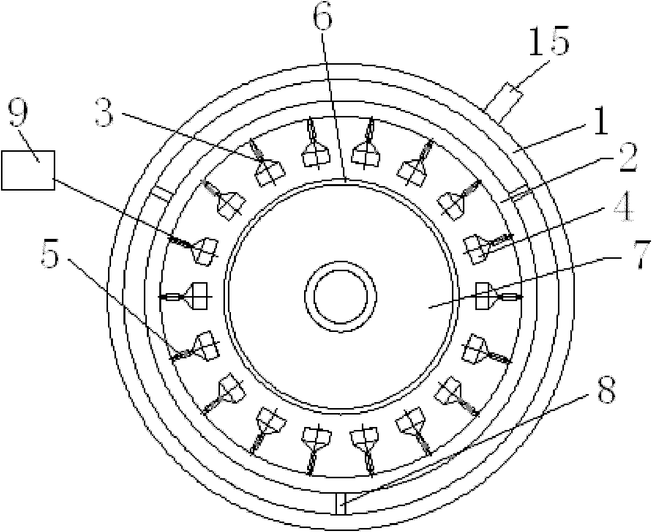
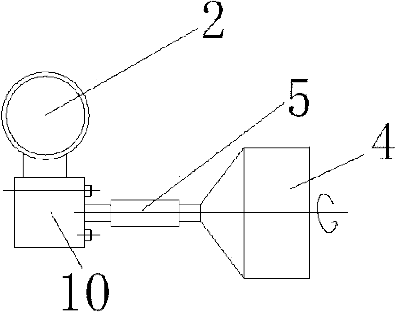
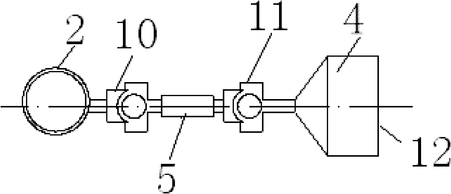
[0029] as attached figure 1 - attached Image 6 As shown, the present invention is a wheel quenching and cooling device, including an outer ring pipe 1, an inner ring pipe 2, a cooling device 3, and a control device 9 for controlling the start and stop of the wheel quenching and cooling device. The cooling device 3 includes a nozzle 4, The nozzle branch pipe 5, the nozzle branch pipe 5 is connected to the inner ring pipe 2, the nozzle 4 is connected to the nozzle branch pipe 5, and the nozzle 4 is arranged to be aligned with the wheel rim 6.

[0030] The inner ring pipe 2 is connected with the outer ring pipe 1 thro...


PUM


Abstract

The invention provides a wheel quenching device applied to the technical field of metal heat treatment. The wheel quenching device comprises an outer ring tube (1), an inner ring tube (2), a cooling device (3) and a control device (9) for controlling the start / stop of the wheel quenching device. The wheel quenching device is characterized in that: the cooling device (3) comprises a nozzle (4) anda nozzle branch pipe (5); the nozzle branch pipe (5) is connected with the inner ring tube (2); and the nozzle (4) is connected with the nozzle branch pipe (5) and has a structure capable of being aligned with a wheel rim (6). By the technical scheme, the wheel quenching device has the advantages that: 1, the depth of an abnormal structure layer of the wheel rim is reduced; 2, the hardness gradient of the section of the wheel rim along the radial direction is improved; 3, the nozzle adjusting mode is improved, so that the adjustment is simple, and the quenching quality is improved; and 4, water splashing is reduced, the work environment for workers in field is improved, the work environment for equipment is improved and the maintenance cost of electric equipment is reduced.

Description

technical field [0001] The invention belongs to the technical field of metal heat treatment, and more specifically relates to a wheel quenching and cooling device. Background technique [0002] The current quenching water spray system adopts high pressure (the pressure in front of the nozzle is 0.38-0.45Mpa), small flow rate (the hourly flow rate of a single nozzle is 2.0-2.5m 3 / h) Atomizing nozzle; the flow rate of the nozzle is high (12.0-18.0m / s), the direction of the nozzle cannot be adjusted, and the adjustment of the direction of the nozzle's water outlet is completed by manually pulling the nozzle pipe connected to the nozzle. When using this water spray method for quenching: 1) Abnormal tissue thickness and layer depth such as bainite appear on the tread surface, and CL60 steel generally has about 10-12mm. 2) The hardness gradient of the rim along the radial direction of the wheel is large, from 5mm to 40mm on the tread surface, the hardness gradient reaches more t...

Claims


Application Information

Patent Timeline
IPC IPC(8): C21D1/667C21D9/00
Inventor 程德利李翔王世付强堃邓荣杰毕翔
Owner MAANSHAN IRON AND STEEL COMPANY
Why Eureka
Try Eureka