
Ion implantation system and method for improving beam current intensity and angle distribution

A technology of ion implantation system and angular distribution, which is applied in the field of ion implantation system and improving beam current intensity and angular distribution, can solve problems such as beam loss, achieve improved current intensity and angular distribution, high beam transmission efficiency, reduce Effect of beam loss

Active Publication Date: 2013-02-13
KINGSTONE SEMICONDUCTOR LIMITED COMPANY
View PDF1 Cites 0 Cited by
  • Summary
  • Abstract
  • Description
  • Claims
  • Application Information

AI Technical Summary

Problems solved by technology

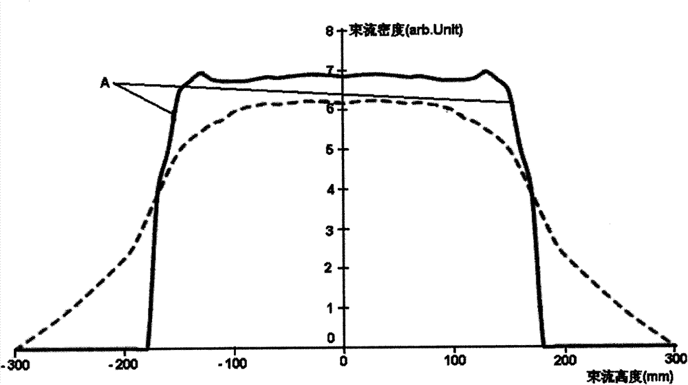
[0007] The technical problem to be solved by the present invention is to overcome the defect that the entrance of the mass analysis magnet will cause a large amount of beam loss in the prior art, and provide a method that can greatly increase the beam current passing through the mass analysis magnet to obtain higher beam transmission Efficient ion implantation system and corresponding method for improving beam current intensity and angular distribution

Method used


Image

  • Ion implantation system and method for improving beam current intensity and angle distribution
  • Ion implantation system and method for improving beam current intensity and angle distribution
  • Ion implantation system and method for improving beam current intensity and angle distribution

Examples


Embodiment Construction

[0021] The preferred embodiments of the present invention are given below in conjunction with the accompanying drawings to describe the technical solution of the present invention in detail.

[0022] Such as figure 2 As shown, the ion implantation system of the present invention includes: an ion source 101 and an extracting system 102, the extracting system 102 is used to extract the ion beam diverging from the ion source 101; a mass analysis magnet 103 is used to extract from the ion beam An ion beam within a preset energy range is selected from the ion beams of the system 102; a beam uniformity controller 104 is used to adjust the longitudinal density distribution of the ion beam within the preset energy range from the mass analysis magnet 103; A calibrator 105 is arranged at the lateral focal point of the mass analysis magnet 103, and is used to make the ion beams in the preset energy range from the beam uniformity controller 104 terminate the divergence trend, become para...


PUM


Abstract

The invention discloses a method for improving beam current intensity and angle distribution in an ion implantation system. Based on current intensity distribution and angle distribution data measured by beam current measurement equipment, the method comprises the following steps of: S1, regulating the driving currents of two dipolar magnets so that the beam currents at the top and the bottom of a beam current path between a leading-out system and a mass analysis magnet deflect to the middle; and S2, regulating a beam current uniformity controller and / or a calibrator so that the beam currents at the top, the middle and the bottom of the beam current path of ion beams in a preset energy range after passing through the calibrator are propagated in parallel. The invention also discloses the ion implantation system. By the method, the beam currents passing through the mass analysis magnet can be greatly promoted and high beam current transmission efficiency can be acquired.

Description

technical field [0001] The invention relates to the field of semiconductor manufacturing, in particular to an ion implantation system and a method for improving beam current intensity and angle distribution. Background technique [0002] Ion implantation is a process of doping impurities in a semiconductor substrate to change the electrical properties and material properties of the substrate. As the production of semiconductor products gradually tends to larger semiconductor wafers (from 8 inches to 12 inches, and now to 18 inches), the single wafer process (processing one wafer at a time) has recently been widely adopted. There are several different processes for doping single wafers. [0003] figure 1 Shown is a kind of ion implantation apparatus disclosed in U.S. Patent 7,326,941, and the apparatus comprises an ion source 101, an extraction system 102 for extracting an ion beam from the ion source 101, and an extraction system 102 for extracting an ion beam from the ion...

Claims


Application Information

Patent Timeline
Patent Type & Authority Patents(China)
IPC IPC(8): C23C14/48
Inventor 陈炯
Owner KINGSTONE SEMICONDUCTOR LIMITED COMPANY
Learn More