Engine cooling system

An engine cooling and engine technology, applied in the direction of engine cooling, engine components, machines/engines, etc., can solve problems such as increased engine fuel consumption, large engine power waste, and large engine economic loss.

Inactive Publication Date: 2011-06-22
WEICHAI POWER CO LTD
View PDF8 Cites 21 Cited by
  • Summary
  • Abstract
  • Description
  • Claims
  • Application Information

AI Technical Summary

Problems solved by technology

[0004] Due to the temperature difference in different seasons and different regions and the relatively harsh working environment of commercial vehicles, when designing the engine cooling system, the models and sizes of the matching water pumps, main cooling fans and radiators are relatively large, so as to meet the needs of the vehicle in The demand for cooling systems under various working conditions, and the proportion of really hot weather in a year is very small, and the proportion of commercial vehicles working in harsh environments is also small, and the driving force of the main cooling fan comes from engine, which causes the heat dissipated by the engine cooling system to not match the heat dissipation required by the engine, which causes a large waste of engine power and a large economic loss of the engine in most of the time; in addition, tests show that, Under the condition that other conditions remain unchanged, as the temperature of the engine outlet water increases, the fuel consumption of the engine will be lower. If the engine is cooled too much, the temperature of the engine outlet water will be lower, which will increase the fuel consumption of the engine.

Method used


Image

  • Engine cooling system
  • Engine cooling system
  • Engine cooling system

Examples


Embodiment Construction

[0027] The core of the present invention is to provide an engine cooling system, the heat dissipation of the engine cooling system matches the required heat dissipation of the engine.

[0028] In order to enable those skilled in the art to better understand the technical solutions of the present invention, the present invention will be further described in detail below in conjunction with the accompanying drawings and specific embodiments.

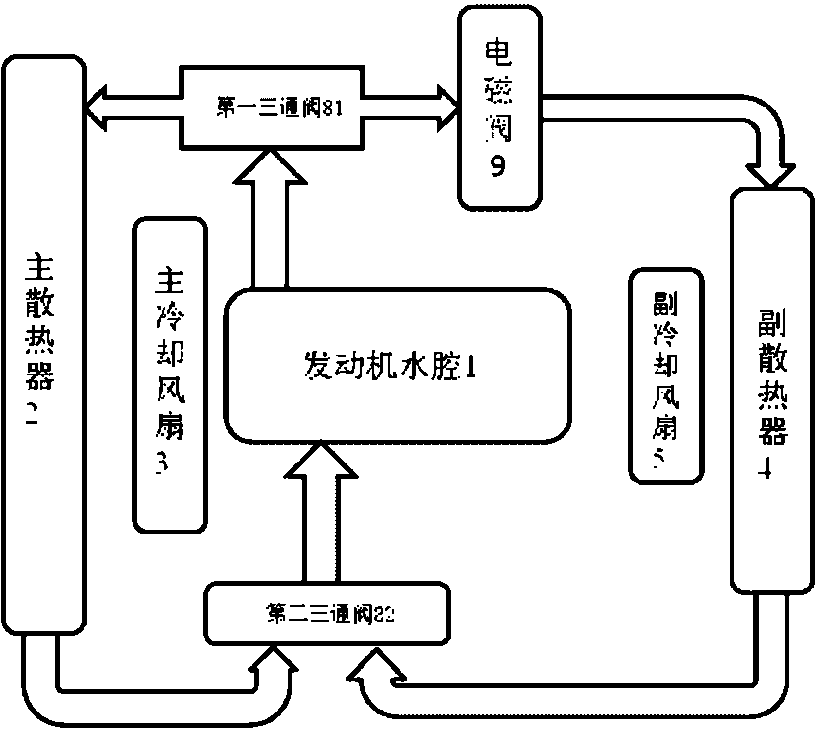
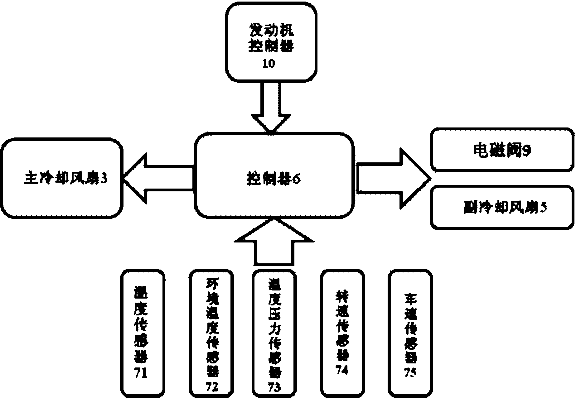
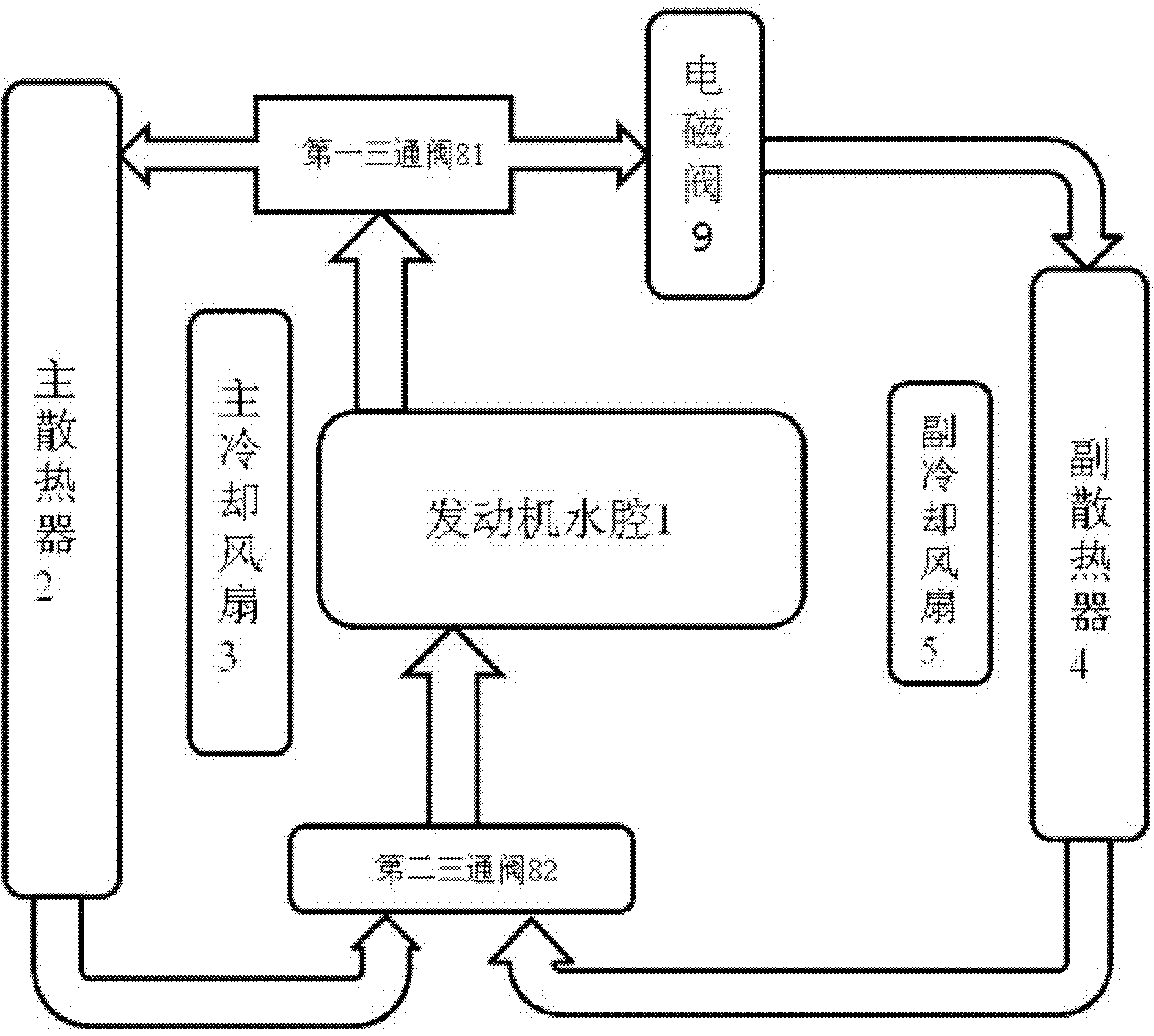
[0029] Please see figure 1 , figure 2 , figure 1 A structural schematic diagram of a specific embodiment of the engine cooling system provided by the present invention; figure 2 for figure 1 Schematic block diagram of the control principle of the engine cooling system.

[0030] Please see figure 1 , figure 2 , figure 1 A structural schematic diagram of a specific embodiment of the engine cooling system provided by the present invention; figure 2 for figure 1 Schematic block diagram of the control principle of the engine coolin...


PUM


Abstract

The invention relates to the technical field of engines, and discloses an engine cooling system. The engine cooling system comprises a main cooling fan, a main radiator, a controller, a temperature sensor, a secondary cooling fan and a secondary radiator, wherein the main radiator is communicated with a water chamber of an engine; the secondary radiator is communicated with the water chamber of the engine; the secondary cooling fan is arranged on a side face of the secondary radiator; a pipeline between the secondary radiator and the water chamber of the engine is provided with a switching valve; the temperature sensor is used for detecting water outlet temperature of the water chamber of the engine and transmitting a water outlet signal to the controller; the controller receives a water temperature signal and judges whether the water outlet temperature is greater than a preset value; and if the water outlet temperature is greater than the preset value, the controller controls the switching valve to be opened and controls the secondary cooling fan to be in a working state. The heat dissipating capacity of the engine cooling system is matched with that required by the engine.

Description

technical field [0001] The invention relates to the technical field of engines, in particular to an engine cooling system whose heat dissipation matches the required heat dissipation of the engine. Background technique [0002] When the engine, especially the diesel engine, is running, the heat generated by combustion and friction will cause the temperature of the piston, cylinder liner, cylinder head, valve, fuel injector and other parts to rise sharply, which will lead to the decline of the mechanical properties of the materials of these parts, resulting in serious damage. Thermal stress, deformation and cracks will also destroy the lubricating oil film and the normal fit clearance of various parts, causing strong wear and tear of parts, even biting, and even fracture accidents; overheating of the engine will also cause inflation to deteriorate, abnormal combustion, and performance degradation. Therefore, the setting of the engine cooling system has a crucial influence on ...

Claims


Application Information

Patent Timeline
Patent Type & Authority Applications(China)
IPC IPC(8): F01P3/20F01P5/02F01P7/16F01P7/08
Inventor 赵晓嵩乔海周张有雷保军
Owner WEICHAI POWER CO LTD
Why Eureka
Try Eureka