
Main pump electromagnetic flywheel of PWR (Pressurized Water Reactor) nuclear power station

A pressurized water reactor nuclear power plant and flywheel technology

Active Publication Date: 2011-06-22
WEIHAI CREDITFAN VENTILATOR
View PDF7 Cites 7 Cited by
  • Summary
  • Abstract
  • Description
  • Claims
  • Application Information

AI Technical Summary

Problems solved by technology

[0009] The present invention mainly solves the limitations of the flywheel energy storage capacity caused by various reasons in the prior art, high requirements for the manufacture of the shafting of the main pump, large vibration energy of the shafting, long start-up time of the main pump, and low power when the main pump starts. For advanced technical problems, provide a voltage that can prolong the idling time of the main pump, reduce the manufacturing requirements of the main pump shaft system, reduce the vibration of the main pump shaft system, shorten the start-up time of the main pump, and reduce the influence of the main pump start-up process on the power bus voltage. Electromagnetic flywheel of main pump of water reactor nuclear power plant

Method used


Image

  • Main pump electromagnetic flywheel of PWR (Pressurized Water Reactor) nuclear power station
  • Main pump electromagnetic flywheel of PWR (Pressurized Water Reactor) nuclear power station

Examples


Embodiment

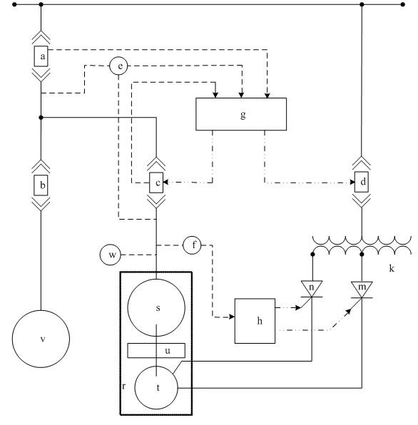
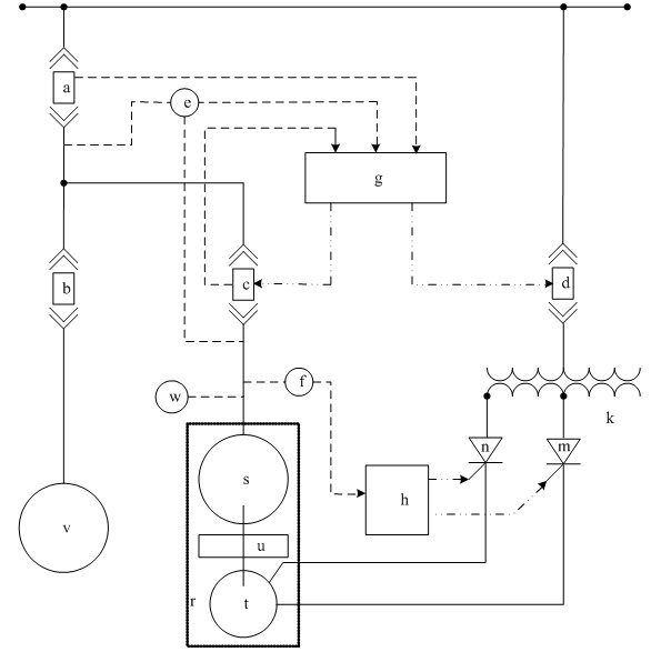
[0020] Embodiment: a kind of pressurized water reactor nuclear power plant main pump electromagnetic flywheel of the present embodiment, such as figure 1 As shown, the main body of the electromagnetic flywheel of the main pump includes a synchronous motor s, a DC starter motor t and a mechanical flywheel u installed on the same shaft, and the above devices are contained in a vacuum sealed container r. Through the synchronous switch c, the power supply of the synchronous motor s and the main pump v can exchange energy with each other. Through the DC starter motor power switch d, the AC transformer k, and the thyristor rectifier power supply m and n, the DC starter motor t directly obtains power from the main pump v power bus. Thyristor rectifier power supplies m and n respectively provide the excitation current and armature current of the DC starter motor t. The starting control unit h controls the starting process according to the outlet frequency of the synchronous motor s. ...


PUM


Abstract

The invention discloses a main pump electromagnetic flywheel of a PWR (Pressurized Water Reactor) nuclear power station, aiming to provide a main pump electromagnetic flywheel of the PWR nuclear power station, substituting the coupling of an electromagnetic field for the mechanical connection between a flywheel and a main pump shafting, greatly improving the main pump running down time by separating a main pump shaft from a flywheel shaft, lowering the manufacture requirements on the main pump shafting, reducing the vibration energy of the main pump shafting, shortening the start time of a main pump and lessening the influence of the main pump start process on peripheral equipment. The main pump electromagnetic flywheel of the PWR nuclear power station comprises a mechanical flywheel, a synchronous motor, a DC start motor, a start control unit and a synchronous control unit, wherein the mechanical flywheel and the synchronous motor are mechanically connected with the rotating shaft ofthe DC start motor, the synchronous motor is connected in parallel with the main pump motor through a switch and a lead, the DC start motor is controlled by the start control unit, the electromagnetic flywheel is started by the DC motor, the synchronous motor keeps synchronous rotation, and the mechanical flywheel, the synchronous motor and the main pump motor jointly provide the main pump with running down energy. The invention is suitable for all PWR nuclear power stations.

Description

technical field [0001] The invention relates to a main pump structure of a pressurized water reactor nuclear power plant, in particular to an electromagnetic flywheel of the main pump of a pressurized water reactor nuclear power plant. Background technique [0002] In the water-cooled reactor nuclear power plant, the main pump is used to provide the reactor coolant circulation power to ensure the effective export of core heat. As a key means to alleviate the power plant's loss of external power supply accidents, the main pump is equipped with a large-mass flywheel to provide sufficient idle time for the main pump after power failure. The traditional design is to directly connect a mechanical flywheel with the main pump shaft to increase the moment of inertia of the shaft system to meet the requirements for idle time. But this also created some problems: [0003] The manufacturing requirements for the pump shaft and individual bearings have become more stringent. The main ...

Claims


Application Information

Patent Timeline
Patent Type & Authority Applications(China)
IPC IPC(8): H02K7/02H02K7/18
CPCY02E60/16Y02E70/30
Inventor 杨子路
Owner WEIHAI CREDITFAN VENTILATOR
Learn More