Liquid crystal driving apparatus

A liquid crystal drive, input voltage technology, applied in the direction of negative feedback circuit arrangement, instrument, DC coupled DC amplifier, etc.

Inactive Publication Date: 2011-06-22
ROHM CO LTD
View PDF9 Cites 21 Cited by
  • Summary
  • Abstract
  • Description
  • Claims
  • Application Information

AI Technical Summary

Problems solved by technology

However, in the above-mentioned common voltage generating circuit f100 having the prior art configuration, since all electric charges are discharged when the element capacitance Clcd is discharged, accumulation of new electric charges must be restarted when the element capacitance Clcd is charged.
Therefore, in the above-mentioned common voltage generating circuit f100 having the prior art configuration, the power consumed by charging and discharging the element capacitance Clcd accounts for a large proportion of the power consumption.

Method used


Image

  • Liquid crystal driving apparatus
  • Liquid crystal driving apparatus
  • Liquid crystal driving apparatus

Examples


Embodiment Construction

[0137] (about overall composition)

[0138] First, the overall structure of a liquid crystal display device or a liquid crystal driver (liquid crystal driver IC) to which the present invention (various technical features mentioned later) is applied will be described in detail with reference to the drawings.

[0139] Figure 28 It is a block diagram showing the overall configuration of a liquid crystal display device to which the present invention is applied. Such as Figure 28 As shown, the liquid crystal display device of this configuration example (or the application such as a mobile phone terminal in which it is installed) has: a liquid crystal display panel xA1; a multiplexer xA2; and a source driving circuit xA3; a gate driving circuit xA4; External DC / DC converter xA5; MPU (Micro Processing Unit) xA6; and image source xA7.

[0140] The liquid crystal display panel xA1 is a TFT (Thin TFT) that uses a liquid crystal element whose light transmittance changes according to...


PUM


Abstract

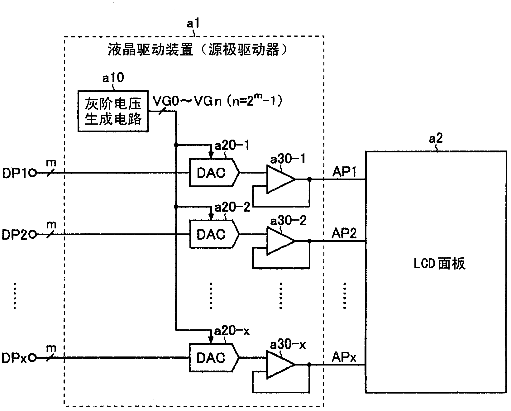
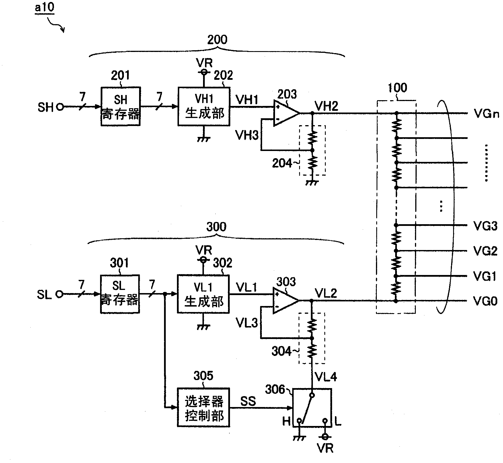
The invention provides a liquid crystal driving apparatus. A voltage amplifier circuit (300) comprises: an input voltage generating unit (302) that generates an input voltage (VL1) based on a set value (SL); an operational amplifier (303) that amplifies the input voltage (VL1) such that the input voltage (VL1) becomes equal to a feedback voltage (VL3), thereby generating an output voltage (VL2); a feedback resistor unit (304) that performs a voltage division between the output voltage (VL2) applied to one end of the feedback resistor unit and a reference voltage (VL4) applied to the other end of the feedback resistor unit, thereby generating the feedback voltage (VL3); a selector control unit (305) that generates a selector control signal (SS) based on the set value (SL); and a selector (306) that selects, based on the selector control signal (SS), the reference voltage (VL4) from a plurality of candidates (GND / VR).

Description

technical field [0001] A number of technical features disclosed in this specification relate to various key technologies applicable to liquid crystal driving devices (liquid crystal driving ICs). Background technique [0002] (1st Background Art) [0003] Figure 8 It is a block diagram showing a conventional example of a voltage amplifying circuit. Such as Figure 8 As shown, the voltage amplifying circuit of this prior art example has: an input voltage generator a100 that generates an input voltage VIN based on a set value S; An operational amplifier a200 for the voltage VOUT; and a feedback resistor a300 for dividing the output voltage VOUT applied to one end and the ground voltage GND applied to the other end to generate a feedback voltage VFB. [0004] In the voltage amplifying circuit having the above configuration, the feedback gain α set by the feedback resistor portion a300 is constant, and the following formula (1) holds between the input voltage VIN and the outp...

Claims


Application Information

Patent Timeline
Patent Type & Authority Applications(China)
IPC IPC(8): H03F1/34G09G3/20G09G3/36H03F3/45
CPCG09G3/3688G09G2330/021G09G2310/0291G09G2330/04G09G2330/025G09G3/3696G09G2310/08G09G2310/0297G09G2330/026
Inventor 矢熊宏司熊谷基也长井崇伊东祐德
Owner ROHM CO LTD
Why Eureka
Try Eureka