
Digital signal processing method and device for micro-mechanical gyroscope

A technology of digital signal processing and micro-mechanical gyro, which is applied in measuring devices, gyro effects for speed measurement, gyroscope/steering sensing equipment, etc., can solve the problem of difficult to accurately measure angular velocity signals and quadrature error signals, and poor linearity of circuits , small dynamic range and other issues, to achieve no spectrum leakage, reduce requirements, and achieve easy results

Inactive Publication Date: 2012-12-12
谢元平
View PDF0 Cites 0 Cited by
  • Summary
  • Abstract
  • Description
  • Claims
  • Application Information

AI Technical Summary

Problems solved by technology

Most of the existing methods are implemented by analog circuits, including analog multipliers or switching multipliers and filters, phase shifters, etc. Such circuits have disadvantages such as poor linearity, small dynamic range, large temperature drift, and difficult debugging.
Existing digital detection methods are difficult to accurately measure angular velocity signals and quadrature error signals

Method used


Image

  • Digital signal processing method and device for micro-mechanical gyroscope
  • Digital signal processing method and device for micro-mechanical gyroscope
  • Digital signal processing method and device for micro-mechanical gyroscope

Examples


Embodiment Construction

[0021] The present invention will be further described in detail below in conjunction with specific embodiments and accompanying drawings.

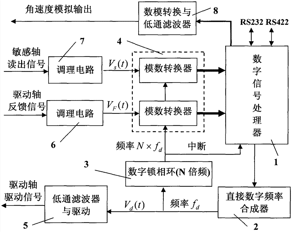
[0022] Such as figure 1 As shown, the micromechanical gyro digital signal processing device of the present invention mainly includes a digital signal processor 1, a direct digital frequency synthesizer 2, a digital phase-locked loop 3, an analog-to-digital converter 4, a low-pass filter and a jitter driving circuit 5, and a driving circuit Feedback signal conditioning circuit 6 , angular velocity readout signal conditioning circuit 7 , digital-to-analog conversion and low-pass filter 8 . The digital signal processor 1 can be a single-chip microcomputer, DSP, FPGA or ASIC chip capable of completing the signal processing described in the present invention. Direct digital frequency synthesizer 2 can be adopted but not limited to AD9952 of Analog Devices. AD9952 contains 14-bit DAC, which can output pure sine wave with adjustable frequency,...


PUM


Abstract

The invention relates to a digital signal processing method and a device for a micro-mechanical gyroscope. The device mainly comprises a digital signal processor, a direct digital frequency synthesizer, a digital phase-locked loop and an analog-to-digital converter. The frequency synthesizer is used for outputting a sine drive signal with controllable frequency and amplitude. A drive feedback signal and an angular velocity readout signal are synchronously converted by the analog-to-digital converter; the converted frequency is an integral multiple of the frequency of the drive signal, and thesampling time length is an integral multiple of the period of the drive signal. With the adoption of the digital signal processor, the sampling data is multiplied by the fixed sine and cosine coefficients, and the input angular velocity and the orthotropic error as well as the phase and the amplitude of the drive feedback signal are resolved in an accumulative manner, and the phase parameters areutilized for adjusting the frequency of the drive signal, so that the frequency of the drive signal follows up the resonance frequency of the gyroscope. The amplitude parameters are utilized for adjusting the amplitude of the drive signal, so that the vibration amplitude is constant. The device realizes the drive of the micro-mechanical gyroscope and the digitization of the angular velocity demodulation, has simple structure and high computation precision, and is easy to produce and transplant in batch.

Description

technical field [0001] The invention relates to the field of micro-electro-mechanical systems, in particular to a micro-mechanical gyroscope digital signal processing method and device, which are used for the control of a vibrating micro-mechanical gyroscope drive circuit and the demodulation output of input angular velocity. Background technique [0002] Micromechanical gyroscopes have the advantages of small size, light weight, and low price, and are widely used in the fields of automobiles, aircraft stability control, weapon system navigation guidance, and micro-satellite attitude control. The common feature of vibrating micromechanical gyroscopes based on the working principle of Coriolis force is that there are two vibration directions perpendicular to each other, namely, the driving vibration direction and the sensitive vibration direction under the Coriolis force. Its working principle is that the inertial mass driving the micro-gyroscope vibrates in the driving axis....

Claims


Application Information

Patent Timeline
Patent Type & Authority Patents(China)
IPC IPC(8): G01C19/5776
Inventor 谢元平
Owner 谢元平
Learn More