Piezoelectric flat panel loudspeaker with distributed ceramic wafers

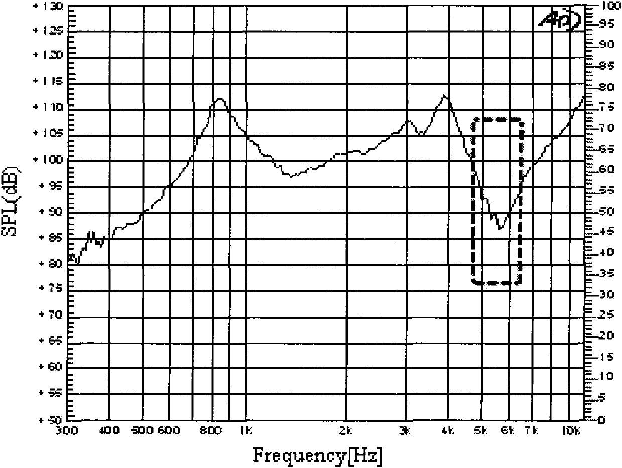
A flat-panel loudspeaker, distributed technology, applied in the direction of piezoelectric/electrostrictive transducers, sensors, electrical components, etc., can solve problems that restrict the popularization and application of piezoelectric loudspeakers, achieve better sound quality, eliminate peaks and The effect of improving the flatness of valley and sound pressure level curves

Active Publication Date: 2011-06-29
KINGTONE INNOVATION BEIJING TECH
View PDF4 Cites 23 Cited by
  • Summary
  • Abstract
  • Description
  • Claims
  • Application Information

AI Technical Summary

Problems solved by technology

Moving the mid-frequency valley back often starts with the structure, size, etc., and the impact of structure, size and other parameters on the performance of the speaker is multifaceted. It is difficult to take care of other adjusted performance indicators while pushing the mid-frequency valley back. , it is often necessary to break the existing design, and it is very difficult to simply push the mid-frequency valley back a few thousand Hz
In terms of reducing or even eliminating the mid-frequency valley at the current frequency, the industry has never had a simple and general method, which has become a problem and bottleneck restricting the popularization and application of piezoelectric speakers.

Method used


Image

  • Piezoelectric flat panel loudspeaker with distributed ceramic wafers
  • Piezoelectric flat panel loudspeaker with distributed ceramic wafers
  • Piezoelectric flat panel loudspeaker with distributed ceramic wafers

Examples


Embodiment 1

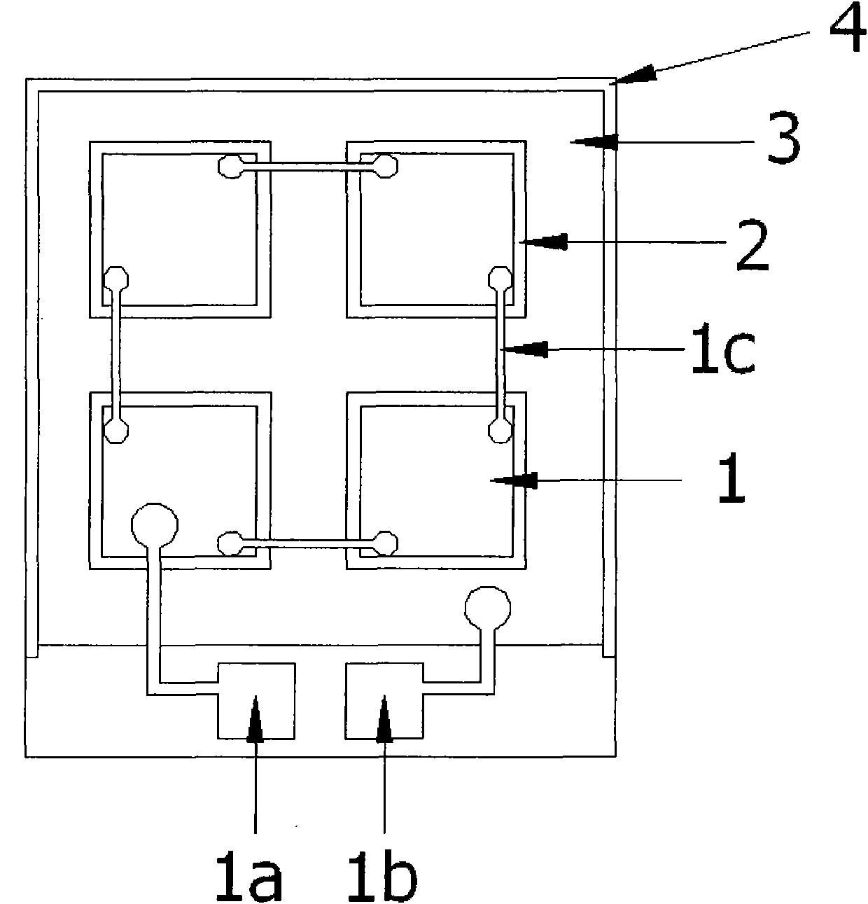
[0038]Figure 3(a) and Figure 3(b) are the front view and exploded view of Embodiment 1 of the present invention. The electrode 1 is divided into a positive electrode and a negative electrode, which are distributed on the upper surface and the lower surface of the piezoelectric ceramic sheet 2 . The piezoelectric ceramic sheet 2 includes four small rectangular sheets, which are pasted on the upper surface of the diaphragm 3 in a two-by-two matrix arrangement or eight small rectangular sheets are respectively bonded on the top of the diaphragm 3, lower surface. The vibrating membrane 3 is rectangular, made of nickel-iron alloy or stainless steel, and the layer thickness is controlled within 30 microns to 100 microns. The frame 4 constrains and fixes the diaphragm 3 . The positive electrode lead 1a and the negative electrode lead 1b respectively lead the positive electrode and the negative electrode to corresponding solder points on the frame to facilitate connection to externa...

Embodiment 2

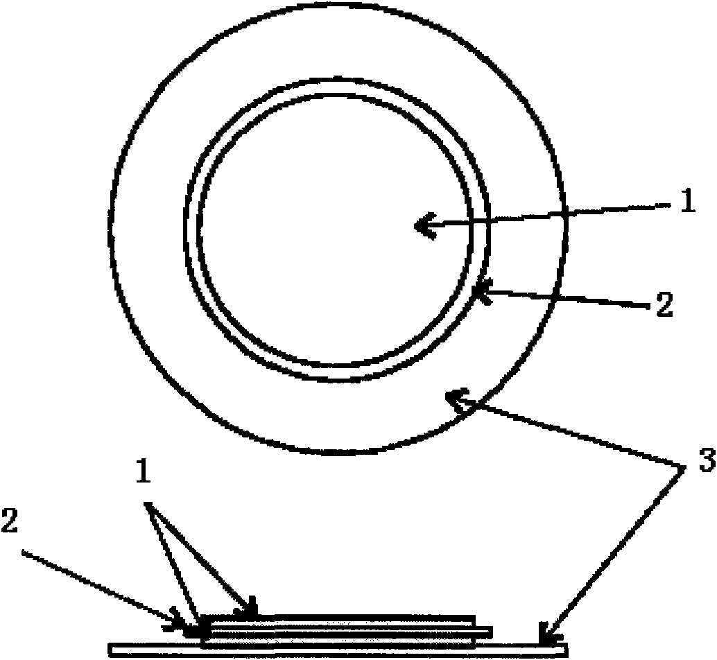
[0040] Figure 5(a) and Figure 5(b) are the front view and exploded view of Embodiment 2 of the present invention. The electrode 1 is divided into a positive electrode and a negative electrode, which are distributed on the upper surface and the lower surface of the piezoelectric ceramic sheet 2 . The piezoelectric ceramic sheet 2 includes four small 90-degree sector-shaped pieces, which are pasted on the upper surface of the diaphragm 3 in an arrangement of 90-degree intervals in a circular array, or eight small 90-degree sector-shaped pieces are respectively bonded to the diaphragm 3's upper and lower surfaces. The vibrating membrane 3 is circular or oval, made of nickel-iron alloy or stainless steel, and the layer thickness is controlled within 30 microns to 100 microns. The frame 4 constrains and fixes the diaphragm 3 . The positive electrode lead 1a and the negative electrode lead 1b respectively lead the positive electrode and the negative electrode to corresponding sold...

Embodiment 3

[0042] Figure 6(a) and Figure 6(b) are the front view and exploded view of Embodiment 3 of the present invention. The electrode 1 is divided into a positive electrode and a negative electrode, which are distributed on the upper surface and the lower surface of the piezoelectric ceramic sheet 2 . The piezoelectric ceramic sheet 2 includes four small rectangular sheets, which are pasted on the upper surface of the diaphragm 3 in a two-by-two matrix arrangement or eight small rectangular sheets are respectively bonded on the top of the diaphragm 3, lower surface. The vibrating membrane 3 also adopts four small vibrating membranes, which are arranged in a two-by-two matrix and correspond one-to-one in space to the four piezoelectric ceramics arranged in a two-by-two matrix. Each small piece of the vibrating membrane 3 They are connected at the junction 3a of the diaphragms of the blocks, and the diaphragm 3 is made of nickel-iron alloy or stainless steel, and the layer thickness ...


PUM


Abstract

The invention belongs to the technical field of loudspeakers, in particular to a thin type piezoelectric speaker with a novel piezoelectric ceramic wafer structure. The thin type piezoelectric speaker structurally comprises a vibration film, piezoelectric ceramic wafers adhered to the vibration film, electrodes on the surfaces of the piezoelectric ceramic wafers, and electrode leading wires connecting the electrodes with an external circuit, and a frame for restricting the vibration film. With the adoption of structure in which an integral piezoelectric ceramic wafer is changed by a plurality of ceramic wafers distributed regularly, the difficulty in the manufacturing process of the piezoelectric ceramic wafers is reduced, the middle-frequency characteristic of the piezoelectric loudspeaker provided by the invention is adjusted, the distortion of acoustic pressure level is reduced, the phase cancellation of middle-frequency sound radiation in the space is reduced and even eliminated, the levelness of acoustic pressure level frequency response curve of the piezoelectric loudspeaker is greatly improved, and the peaks and valleys of the middle-frequency acoustic pressure level frequency response curve can be eliminated under the situation that the parameters are appropriate. Therefore, the tone quality of the piezoelectric loudspeaker is better.

Description

technical field [0001] This patent relates to a new piezoelectric speaker, more specifically, a thin piezoelectric speaker with a new diaphragm structure. Background technique [0002] The loudspeaker is an electric-force-acoustic transducer, which is an important component in audio equipment. Loudspeakers are widely used in people's daily life and bring a lot of convenience. In the fields of electronic products such as automobiles, radio, TV, speakers, mobile phones, MP4, computers, etc., the applications of loudspeakers can be seen almost everywhere. There are many types of loudspeakers, which can be divided into electric type (ie moving coil type), electrostatic type (ie capacitive type), electromagnetic type (ie reed type), piezoelectric type, etc. according to their energy conversion principles; Divided into woofers, midrange speakers, and tweeters, among which dynamic speakers are the most widely used. Due to its small size, thinness and lightness, the piezoelectric ...

Claims


Application Information

Patent Timeline
Patent Type & Authority Applications(China)
IPC IPC(8): H04R17/00
Inventor 袁世明
Owner KINGTONE INNOVATION BEIJING TECH
Why Eureka
Try Eureka