Positioning and bone-cutting system used for minimally invasive artificial knee joint replacement

An artificial knee joint and positioning system technology, applied in the field of positioning and osteotomy systems, can solve the problems of difficult fixation and aiming of positioning instruments, complex structure, operation steps, long operation time, etc., to achieve accurate control of precision and depth, reduce Surgical wound area, fast and accurate effect of osteotomy

Inactive Publication Date: 2011-07-06
徐栋梁 +1
View PDF3 Cites 19 Cited by
  • Summary
  • Abstract
  • Description
  • Claims
  • Application Information

AI Technical Summary

Problems solved by technology

[0005] At present, most of the foreign MIS-TKA surgical instruments and tools are just the original TKA instruments and tools proportionally smaller, which do not match the incision.
In particular, positioning instruments are difficult to fix and aim during MIS-TKA. Osteotomy instruments are placed perpendicular to the incision. It is difficult to prevent iatrogenic damage to surrounding soft tissues during osteotomy, which seriously affects the accuracy of osteotomy and prosthesis installation. Therefore, in general, in the traditional minimally invasive artificial knee replacement surgery, whether it is the positioning system or the osteotomy system, there are many components, large volume, complex structure and operation steps, long operation time and large wounds. Unsatisfactory results of surgery

Method used


Image

  • Positioning and bone-cutting system used for minimally invasive artificial knee joint replacement
  • Positioning and bone-cutting system used for minimally invasive artificial knee joint replacement
  • Positioning and bone-cutting system used for minimally invasive artificial knee joint replacement

Examples


Embodiment Construction

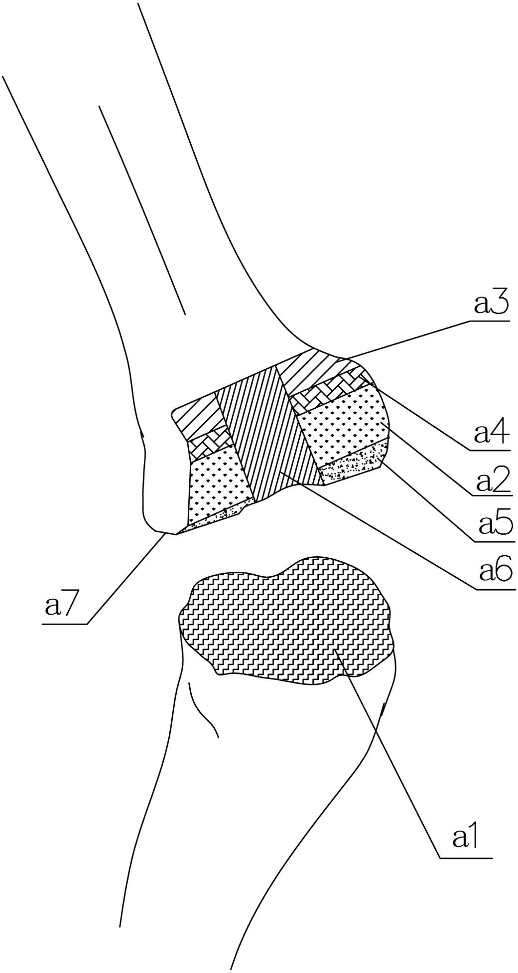
[0032] refer to Figure 1 to Figure 12 A positioning and osteotomy system for minimally invasive artificial knee replacement, which includes a positioning system and an osteotomy system, the positioning system includes several reference modules and a positioning blocking module connected with the reference modules, the osteotomy system Including several osteotomy drills and osteotomy saws, as well as the patella trimming drill 6 for trimming the patella and the osteotomy surface trimming drill 7 for trimming the osteotomy surface, the osteotomy drill and the osteotomy saw are blocked by positioning during work Module limit.

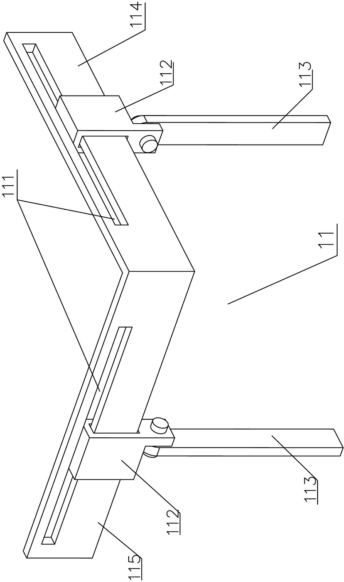
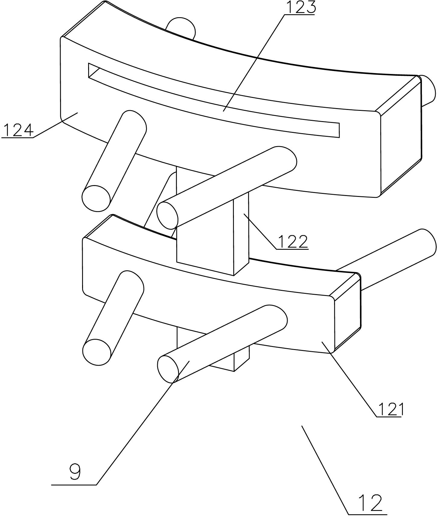
[0033] refer to figure 2 and image 3 , further as a preferred embodiment, the reference module includes a tibial osteotomy surface determining module 11 , and the positioning blocking module includes a tibial osteotomy thickness control module 12 cooperating with the tibial osteotomy surface determining module 11 .

[0034] Further as a preferred emb...


PUM


Abstract

The invention discloses a positioning and bone-cutting system used for minimally invasive artificial knee joint replacement, which comprises a positioning sub-system and bone-cutting sub-system, wherein the positioning sub-system comprises a plurality of reference modules and a positioning barrier module coupled with the reference modules; the bone-cutting sub-system comprises a plurality of bone-cutting drills, a plurality of bone-cutting saws, a patella trimming drill used for trimming a patella and a bone cut section trimming drill used for trimming a bone cut section; and the bone-cutting drills and the bone-cutting saws are limited by the positioning barrier module during the operation. In the positioning and bone-cutting system used for the minimally invasive artificial knee joint replacement, the positioning sub-system and the bone-cutting sub-system cooperate to accurately control the bone-cutting precision and the bone-cutting depth, reduce the wound area and protect the soft tissues. The positioning and bone-cutting system used for the minimally invasive artificial knee joint replacement has a simple structure, is easy to use, achieves the effect of rapidly and accurately positioning and cutting the bone, and can be widely applied to minimally invasive artificial knee joint replacement.

Description

technical field [0001] The invention relates to an auxiliary device for minimally invasive artificial knee replacement, in particular to a positioning and osteotomy system for minimally invasive artificial knee replacement. Background technique [0002] The knee joint is one of the most important sports organs in the human body, and its injury rate is also the highest. WHO estimates that knee osteoarthritis (OA) alone causes as much disability as chronic heart and lung disease in people over 60 years of age. Due to the rising incidence of longevity, obesity, trauma, etc., the incidence of knee OA is increasing. The end-stage (pain, dysfunction, etc.) of almost all knee diseases must be addressed by total knee arthroplasty (TKA). The concept of TKA is to make a surgical incision at the knee joint, use the osteotomy system to cut off the redundant part of the joint between the femur and the tibia, and then install a prosthesis that matches the cut, so as to complete the arti...

Claims


Application Information

Patent Timeline
Patent Type & Authority Applications(China)
IPC IPC(8): A61B19/00A61B17/56A61B17/14A61B17/16A61B90/11
Inventor 徐栋梁朱琦
Owner 徐栋梁
Why Eureka
Try Eureka