Device and method used for spraying liquid

A spraying device and liquid technology, applied in the spraying device to generate the spray to be applied to the object, can solve the problems of long working time, high energy consumption, large nozzle wear, etc., to reduce labor costs, avoid material accumulation, The effect of reducing energy consumption

Inactive Publication Date: 2011-07-06
EIC GRP GMBH (DE)
View PDF9 Cites 5 Cited by
  • Summary
  • Abstract
  • Description
  • Claims
  • Application Information

AI Technical Summary

Problems solved by technology

This means that about 60% to 70% of the material used is not attached to the object, that is to say is not used efficiently
Furthermore, with regard to the mass effect of conventional spraying methods, there is the risk of spray markings - i.e. uneven / uneven surfaces, resembling (painted) orange peel / bubbles - forming on objects
Corners and edges may be difficult to machine to optimum effect
In addition, the nozzles are subject to greater wear due to the use of the material to be sprayed or the high through-flow (volume)
Finally, the inefficiency of material application also has an economic impact, since the jetting process results in high energy consumption, expensive raw material usage and long operating times

Method used


Image

  • Device and method used for spraying liquid
  • Device and method used for spraying liquid
  • Device and method used for spraying liquid

Examples


Embodiment Construction

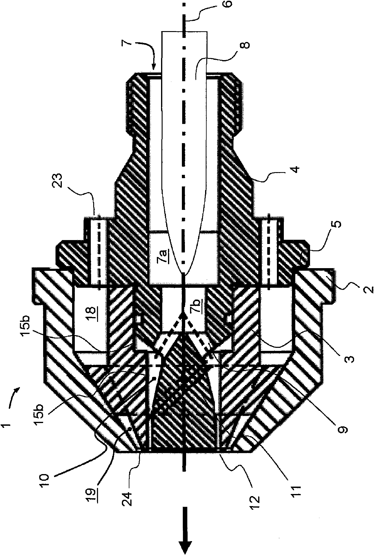
[0023] exist figure 1 A spraying device 1 with three main components—hood 2 , air guide body 3 and nozzle body 4 is shown in . figure 1 The sprinkler device 1 is shown in the assembled state, ie the hood 2 is pushed over the air guide body 3 and the air guide body is accommodated inside the hood. Furthermore, a part of the nozzle body 4 is arranged in the interior of the air guide body 3 . Furthermore, the cover 2 extends onto the flange 5 of the nozzle body 4 . Inside the nozzle body 4 there is arranged concentrically to the longitudinal axis 6 of the spraying device an opening 7 for feeding the material to be sprayed. The orifice 7 for material delivery is located in the first inner section 7a of the nozzle body 4 towards the spraying device 1 at the figure 1 The end on the left in the center extends, i.e. in the direction of spraying (in figure 1 shown by an arrow) extends. Adjacent to the first inner section 7a of the nozzle body 4 is a second section 7b whose inner d...


PUM


Abstract

The invention relates to a method used for pneumatically spraying liquid especially such as colourant, enamel paint, paint, and the like and generating spray that is applied to an object, wherein the method is characterized in that a spraying device (1) is utilized. In the method, liquid basically departs from the spraying device (1) under zero pressure. Spraying air in the spraying device is formed through rotation at a first angle (14) relative to a longitudinal axis (6) of the spraying device and at a second angle (21) relative to an axes (22) perpendicular to the longitudinal axis (6) of the spraying device, so that spraying air can depart from the spraying device in a whirlwind manner. The first angle (14) ranges from 25 to 40 degrees, and the second angle (21) ranges from 35 to 55 degrees. Liquid is sprayed by spraying air after departing from the spraying device.

Description

technical field [0001] The present invention relates to a device for pneumatic spraying / atomization Liquids - especially paints, enamels, lacquers, etc. - and methods for producing sprays to be applied to objects. Furthermore, the invention relates to a spraying device for carrying out the method. Background technique [0002] During the pneumatic spraying of liquids, for example by means of enamel sprayers, or within the scope of the painting process, the material to be sprayed—usually a liquid—flows through a sprayer, and the liquid then leaves the nozzle under high pressure. After leaving the nozzle, the liquid is sprayed into a spray by adding spray air, wherein the compressed air leaving a dedicated air nozzle or air port conditions and forms the spray there. [0003] A spray nozzle arrangement for spraying by mixing with external air is known, for example, from DE 112006002295 T5. where a liquid under pressure is supplied to the nozzle body, said liquid leaves the ...

Claims


Application Information

Patent Timeline
Patent Type & Authority Applications(China)
IPC IPC(8): B05B7/10
Inventor H-J·蒂勒
Owner EIC GRP GMBH (DE)
Why Eureka
Try Eureka