Powder coating device and method

A technology of powder coating and powder coating, applied in the direction of spraying device, spray discharge device, spray electric energy device, etc., can solve the problem of reducing the quality of coating film

Inactive Publication Date: 2007-07-18
PARKER ENGINEERING
View PDF2 Cites 0 Cited by
  • Summary
  • Abstract
  • Description
  • Claims
  • Application Information

AI Technical Summary

Problems solved by technology

That is, the surface potential of the coating film gradually increases due to the application of the charged powder coating, causing insulation breakdown between the surface of the object to be coated and the surface of the coating film, whereby this part of the gas releases positive ions through ionization, The positive ions are neutralized with the negative ions generated by corona discharge, thereby causing so-called backionization, thereby degrading the quality of the coating film

Method used


Image

  • Powder coating device and method
  • Powder coating device and method
  • Powder coating device and method

Examples


Embodiment approach 1

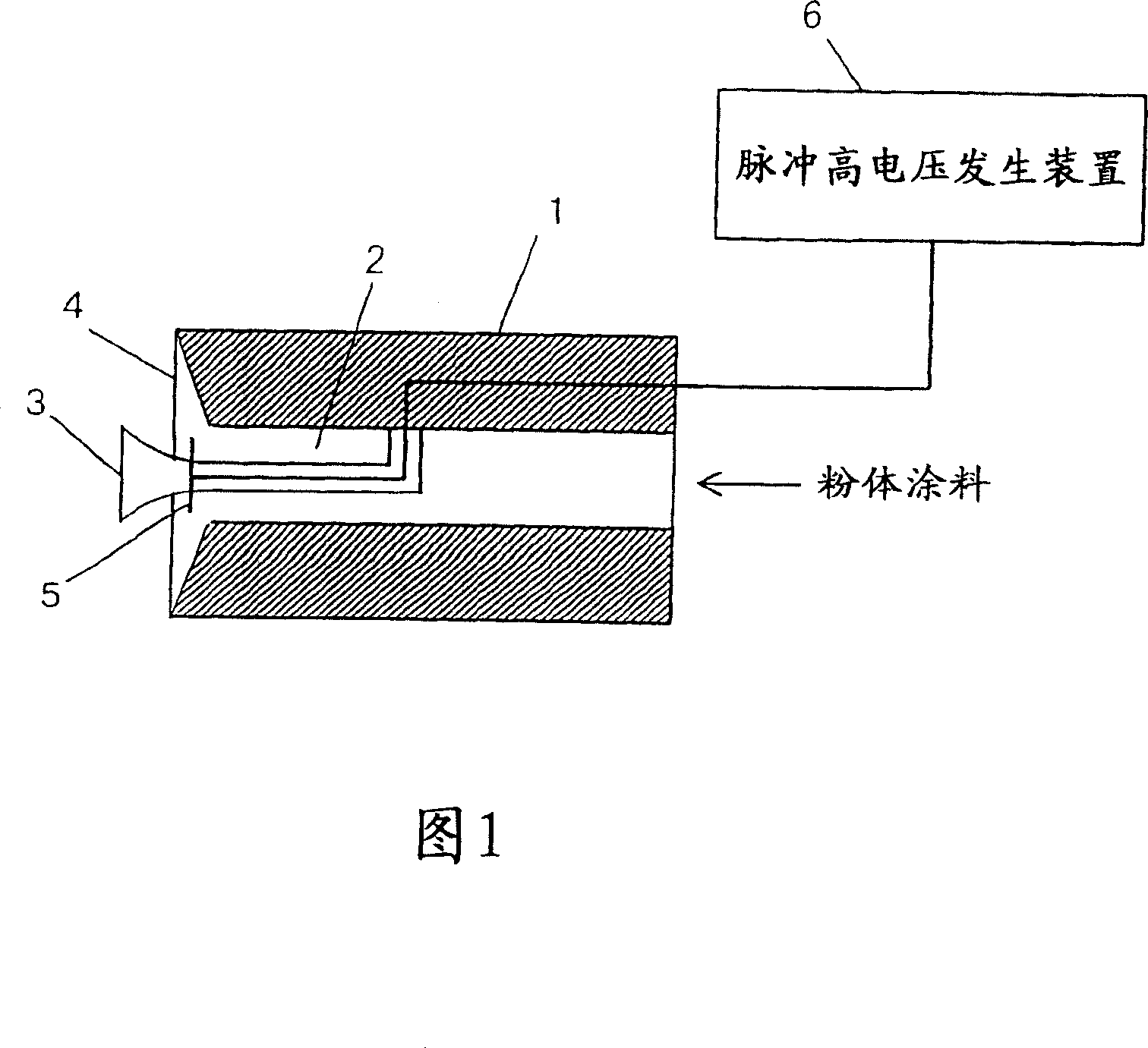
[0018] FIG. 1 shows the configuration of a powder coating apparatus according to Embodiment 1 of the present invention. The powder coating device has a substantially cylindrical spray gun body 1 , and a powder flow path 2 is formed on the central axis of the spray gun body 1 . The powder channel 2 is formed into a cylindrical shape along the outer periphery of the diffuser 3 , and is connected to the annular nozzle opening 4 at the front end of the spray gun body 1 . Inside the nozzle opening 4 , a plurality of pin-type corona electrodes 5 held by the diffusion device 3 are provided to protrude radially. Each corona electrode 5 is electrically connected to each other and connected to a pulse high voltage generating device 6 .

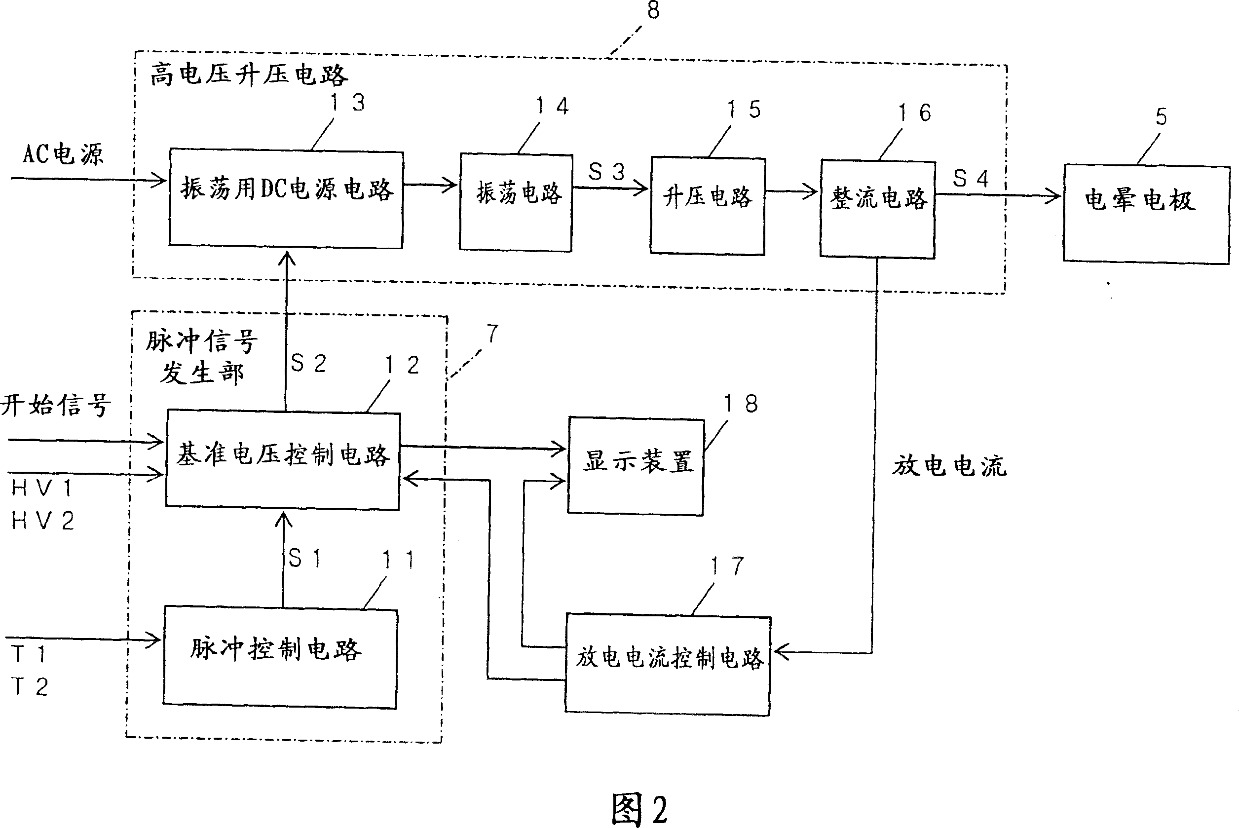
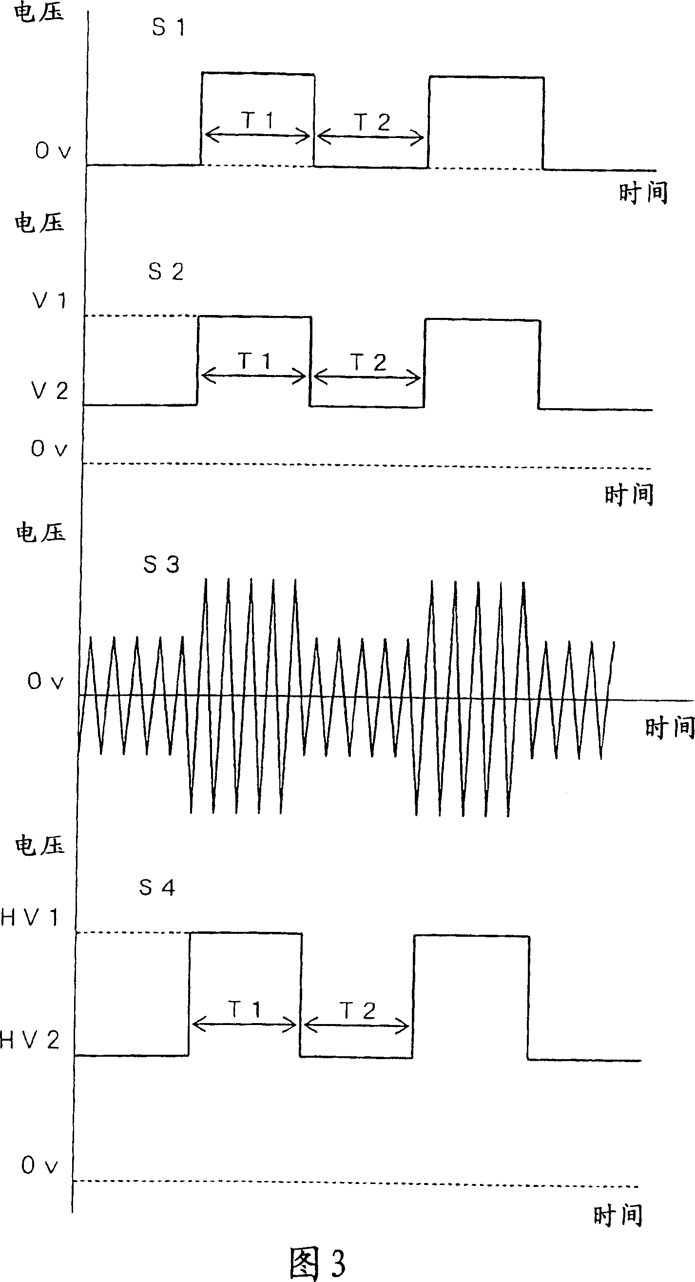
[0019] The circuit structure of the pulse high voltage generating device 6 is shown in FIG. 2 . The pulse high voltage generating device 6 has a pulse signal generating circuit 7 that generates a low voltage pulse signal, and a high voltage applicatio...

Embodiment approach 2

[0031]The circuit structure of the pulse high voltage generator used in Embodiment 2 is shown in FIG. 4 . In this pulse high voltage generator, the mode selection circuit 31 is connected to the pulse signal generator circuit 7 in the pulse high voltage generator of Embodiment 1 shown in FIG. 2 . In the mode selection circuit 31, peak values ​​suitable for a plurality of coating modes, such as a thick coating mode, a thin coating mode, a penetrating mode for coating to a concave portion, and a recoating mode for repeatedly coating on a cover film, are stored in advance. Combination of voltage HV1, base voltage HV2, pulse width T1 and pulse interval T2.

[0032] When the operator turns on a switch not shown in the figure by selecting one of the coating modes in the mode selection circuit 31, the pulse width T1 and the pulse interval T2 stored corresponding to the selected coating mode are input to the pulse control Circuit 11 , peak voltage HV1 and base voltage HV2 are input to...

Embodiment approach 3

[0035] The powder coating device according to the third embodiment has the same structure as the powder coating device according to the first embodiment shown in FIG. 1 is different.

[0036] The circuit structure of the pulse high voltage generator used in the third embodiment is shown in FIG. 5 . This pulse high voltage generator has a high voltage application circuit 8 for applying a high voltage signal So to the corona electrode 5 . The high voltage applying circuit 8 is the same as that used in Embodiment 1, and it is composed of an oscillating DC power supply circuit 13, an oscillating circuit 14, a booster circuit 15, and a rectifying circuit 16 connected in series, and the external AC power supply and the oscillating DC The power supply circuit 13 is connected. The discharge current control circuit 19 is connected to the rectifier circuit 16 of the high voltage application circuit 8 , and the oscillation DC power supply circuit 13 is connected to the discharge curren...


PUM


Abstract

A powder coating device, wherein a low-voltage pulse signal (S2) generated in a pulse signal generation circuit (7) is boosted to a high voltage in a high voltage application circuit (8) to be applied to a corona electrode (5). This enable corona discharging to be generated intermittently toward an object from the corona electrode (5), powder paint jetted forward from the nozzle opening of a gun body to be charged by negative ions produced by corona discharging, and then charged powder paint to be sent toward the object for coating on the surface of the object.

Description

technical field [0001] The present invention relates to a powder coating device and method, and more particularly, to a coating device and method for spraying charge onto a powder coating and applying it to an object to be coated using static electricity. Background technique [0002] From the viewpoint of environmental protection, electrostatic powder coating is attracting attention as a pollution-free coating method that does not use solvents and is good for the environment. In this electrostatic powder coating, powder paint is supplied from a paint tank through an injector to a coating gun, and is sprayed onto an object to be coated through a nozzle opening formed at the tip of the coating gun along with a conveying air flow. At this time, a high voltage is applied to a corona electrode provided at the tip of the coating gun, and the object to be coated is grounded, thereby generating corona discharge from the electrode of the coating gun to the object to be coated. As a...

Claims


Application Information

Patent Timeline
Patent Type & Authority Patents(China)
IPC IPC(8): B05B5/053B05B5/025B05B5/03B05B5/10
CPCB05B5/10B05B5/032
Inventor 森田忠夫村井浩树屋部幸诚中村哲
Owner PARKER ENGINEERING
Why Eureka
Try Eureka