Condensate pump used in nuclear power station

A technology for condensate pumps and nuclear power plants, which is applied to the components, pumps, and pump elements of the pumping device for elastic fluids, which can solve the problems that the strength and rigidity of the outer cylinder are not high enough, the overall weight and cost of the pump group are high, and the pump is affected. Group service life and other issues, to achieve the effect of increasing strength and stiffness, good support, and reducing overall weight

Active Publication Date: 2011-07-06
SHANGHAI APOLLO MACHINERY
View PDF4 Cites 4 Cited by
  • Summary
  • Abstract
  • Description
  • Claims
  • Application Information

AI Technical Summary

Problems solved by technology

The entire pump body structure of the condensate pump in the prior art is: a double-suction volute case, a secondary guide vane, a final guide vane, a straight pipe, and a water outlet shell connected sequentially from bottom to top; due to the long cantilever, the operation is stable Poor sex
Since the secondary guide vane and the final guide vane are far away from the driving end of the pump shaft, the vibration caused by the rotation of the secondary guide vane and the final guide vane is relatively large, and the pressure on the straight pipe is also relatively large. Larger straight pipes, not only less stable pump set, but also higher overall weight and cost of the pump set
In addition, the double-suction volute case, secondary guide vanes, final guide vanes and straight pipes constitute a cantilever structure as a whole, which is prone to unequal expansion caused by thermal effects, and the thermal strain of the connecting parts in the unit is also relatively large; In addition, there is no reinforcing ring rib on the outer surface of the outer cylinder, so that the strength and rigidity of the outer cylinder are not high enough, thus affecting the service life of the pump set

Method used


Image

  • Condensate pump used in nuclear power station
  • Condensate pump used in nuclear power station
  • Condensate pump used in nuclear power station

Examples


Embodiment Construction

[0014] In order to better understand the technical solution of the present invention, it will be described in detail below through specific embodiments in conjunction with the accompanying drawings:

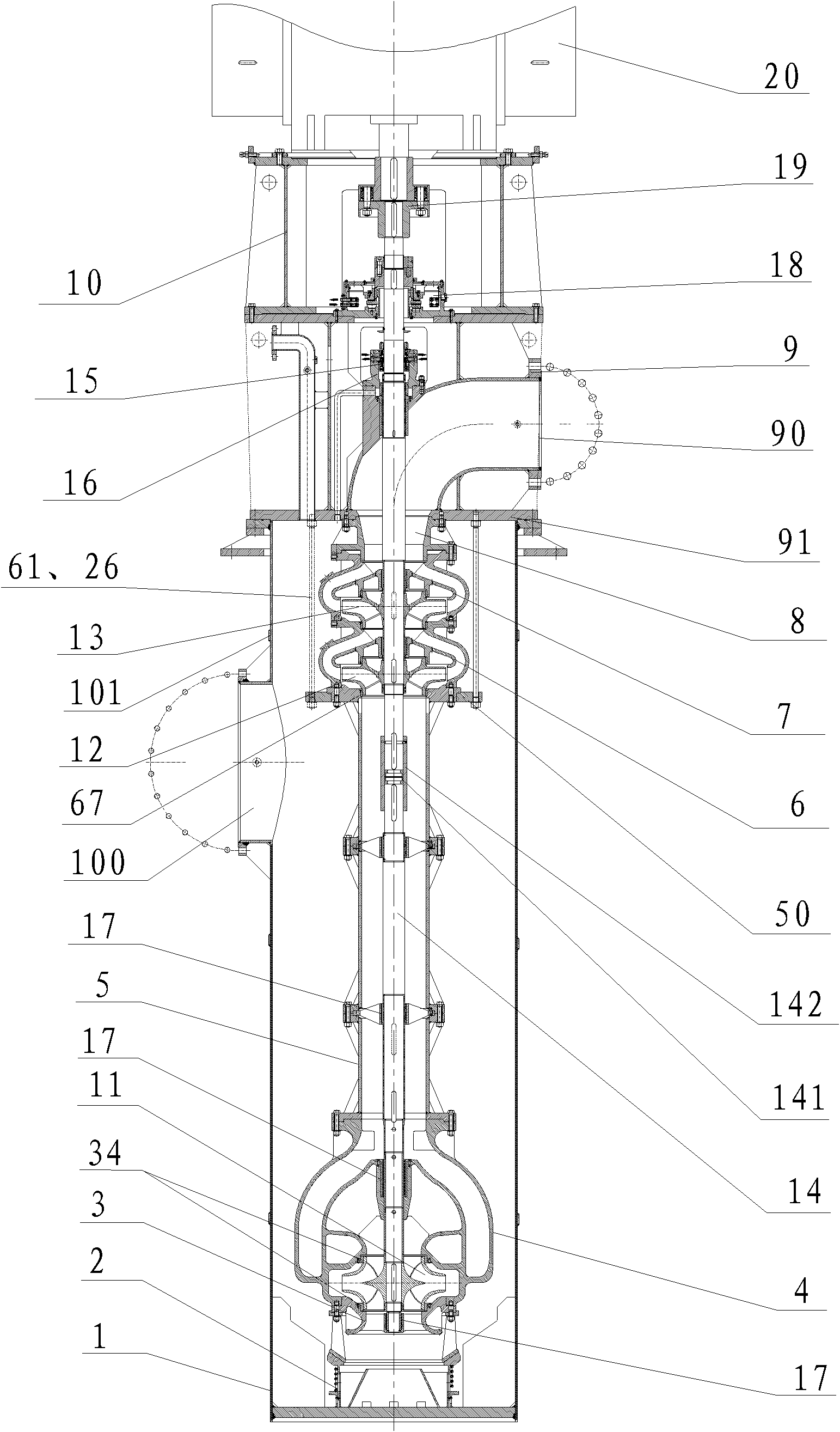
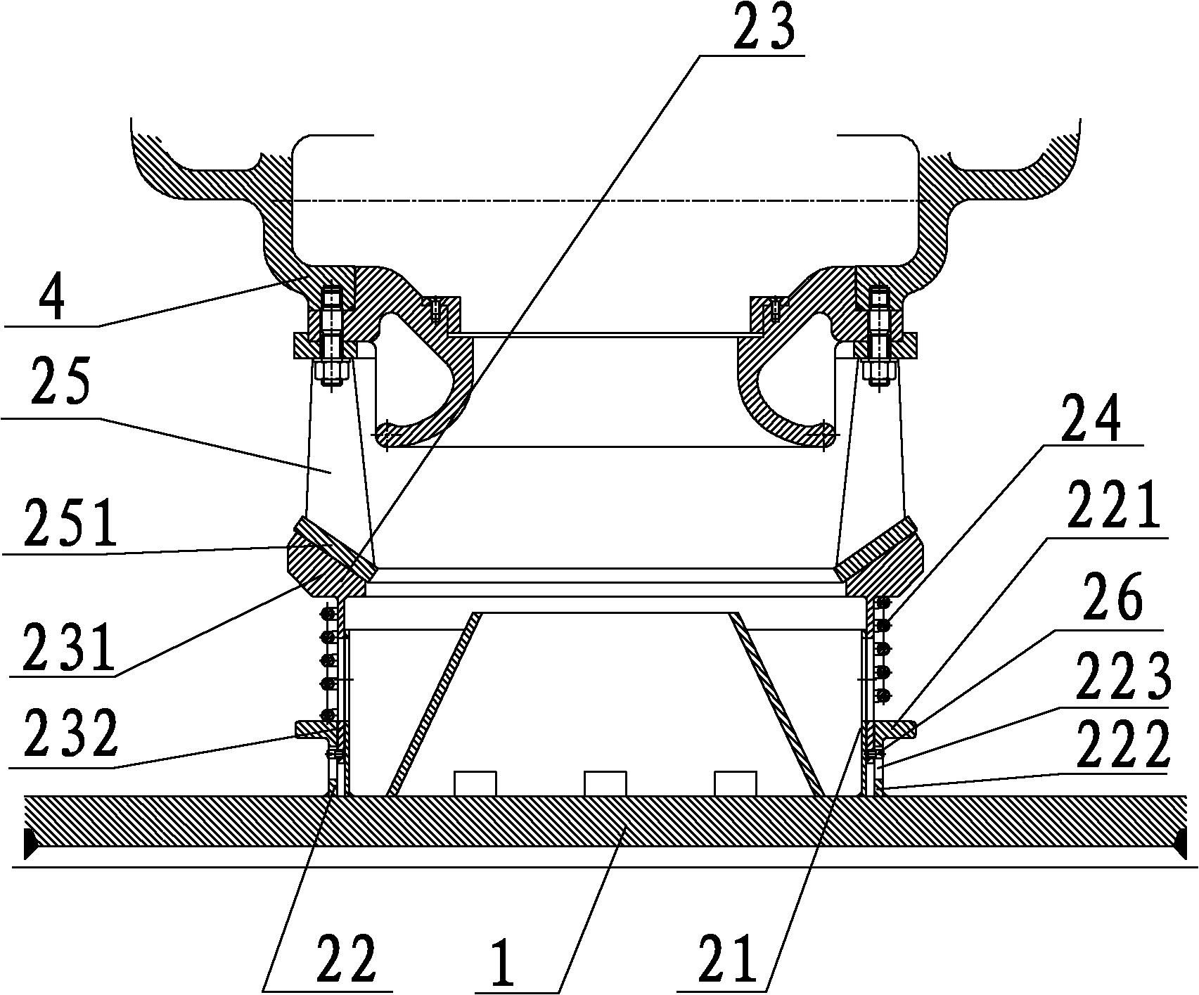
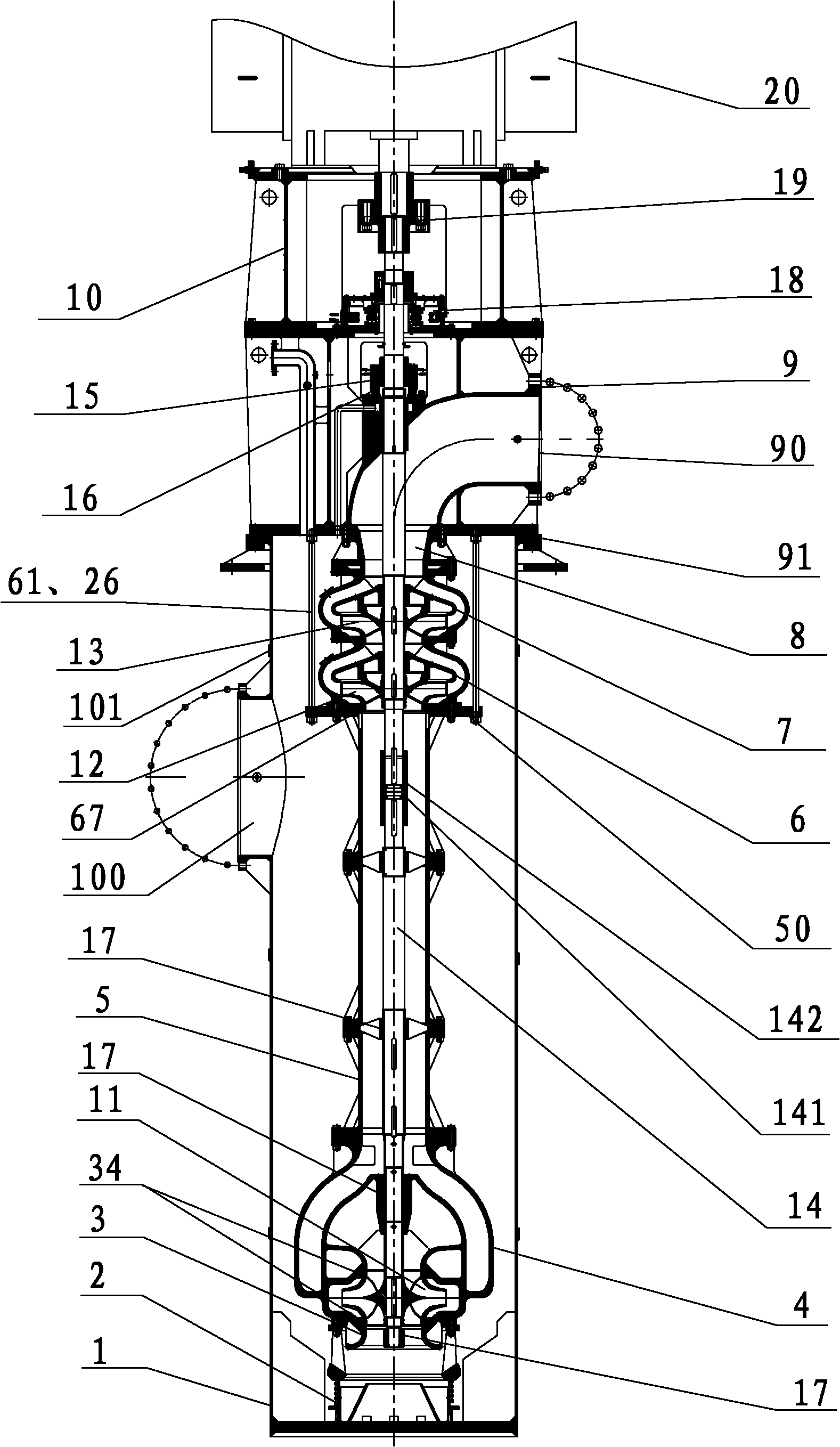
[0015] see figure 1 , The condensate pump for nuclear power plants of the present invention includes a vertical outer cylinder 1, an auxiliary support device 2, a pump body, a motor frame 10, a first stage impeller 11, a secondary impeller 12, a final stage impeller 13, a pump shaft 14, Mechanical seal 15, bearing assembly and motor 20, wherein:

[0016] The pump body includes a water inlet horn 3, a double-suction volute case 4, a straight pipe 5, a secondary guide vane 6, a final guide vane 7, a different-diameter housing 8 and a water outlet shell, which are coaxially connected to each other in sequence from bottom to top. body 9; the water outlet shell 9 is fixed on the upper end of the outer cylinder 1, the water inlet horn 3, the double-suction volute case 4, the straight ...


PUM


Abstract

The invention discloses a condensate pump used in a nuclear power station. The condensate pump comprises an outer cylinder body, a pump body, a water outlet case body, a motor frame, a pump shaft, a first stage impeller, a second stage impeller, a last stage impeller, a mechanical seal, a bearing component and a motor, wherein the motor frame is fixed at the upper end of the water outlet case body; the mechanical seal is arranged in an inner cavity of the water outlet case body through a seal case body; the bearing component comprises a plurality of guide bearings and a vertical thrust bearing; the motor is fixed at the upper end of the motor frame and connected to the upper end of the pump shaft; the pump body comprises a double-suction spiral case body, a straight pipe, the second stage guide vane and the last stage guide vane which are arranged in an inner cavity of the outer cylinder body and coaxially connected with each other in sequence from bottom to up; the water outlet case body is fixed at the upper end of the outer cylinder body and connected with the last stage guide vane; a flange mounted on the peripheral surface of a top plate of the straight pipe is connected with a bottom plate of the water outlet case body through a plurality of penetrating rods and nuts which are evenly distributed in the radial direction, so as to grip the second stage guide vane and the last stage guide vane; and an auxiliary support device is further arranged between the pump body and the outer cylinder body.

Description

technical field [0001] The invention relates to a centrifugal pump, in particular to a condensate pump used in nuclear power plants. Background technique [0002] Condensate pumps are used to pump condensate in nuclear power plants. The suction side of the pump is highly vacuumed, which is prone to cavitation and air inhalation. Therefore, the requirements for anti-cavitation of the pump are particularly high, and the head is as high as 150 to 350 meters. The entire pump body structure of the condensate pump in the prior art is: a double-suction volute case, a secondary guide vane, a final guide vane, a straight pipe, and a water outlet shell connected sequentially from bottom to top; due to the long cantilever, the operation is stable Sex is poor. Since the secondary guide vane and the final guide vane are far away from the driving end of the pump shaft, the vibration caused by the rotation of the secondary guide vane and the final guide vane is relatively large, and the p...

Claims


Application Information

Patent Timeline
Patent Type & Authority Applications(China)
IPC IPC(8): F04D29/42F04D29/22F04D29/046
Inventor 陆金琪
Owner SHANGHAI APOLLO MACHINERY
Why Eureka
Try Eureka