Slag discharge device in dust removal and desulfurization system

A desulfurization system and slag discharge pipe technology, which is applied to the feeding/discharging device of the sedimentation tank, the separation of dispersed particles, chemical instruments and methods, etc. And other issues

Inactive Publication Date: 2011-07-13
BAODING RUNLI ENERGY SAVING & ENVIRONMENTAL PROTECTION
View PDF3 Cites 0 Cited by
  • Summary
  • Abstract
  • Description
  • Claims
  • Application Information

AI Technical Summary

Problems solved by technology

This method is time-consuming, labor-intensive, inefficient, greatly affected by the environment, and poor working conditions
Especially during slag removal, it is necessary to stop the operation or empty the upper liquid in the sedimentation tank to clean and remove slag, which seriously affects the effect of dust removal and desulfurization
[0003] To sum up, the fundamental defect of the slag removal methods currently used in the dust removal and desulfurization system is that the automatic cleaning and slag removal of the desulfurization slag in the sedimentation tank cannot be realized.
Moreover, the equipment investment is large, the operating cost is high, the efficiency is low, and the cleaning effect of desulfurization slag is not good, etc.

Method used


Image

  • Slag discharge device in dust removal and desulfurization system
  • Slag discharge device in dust removal and desulfurization system
  • Slag discharge device in dust removal and desulfurization system

Examples


Embodiment Construction

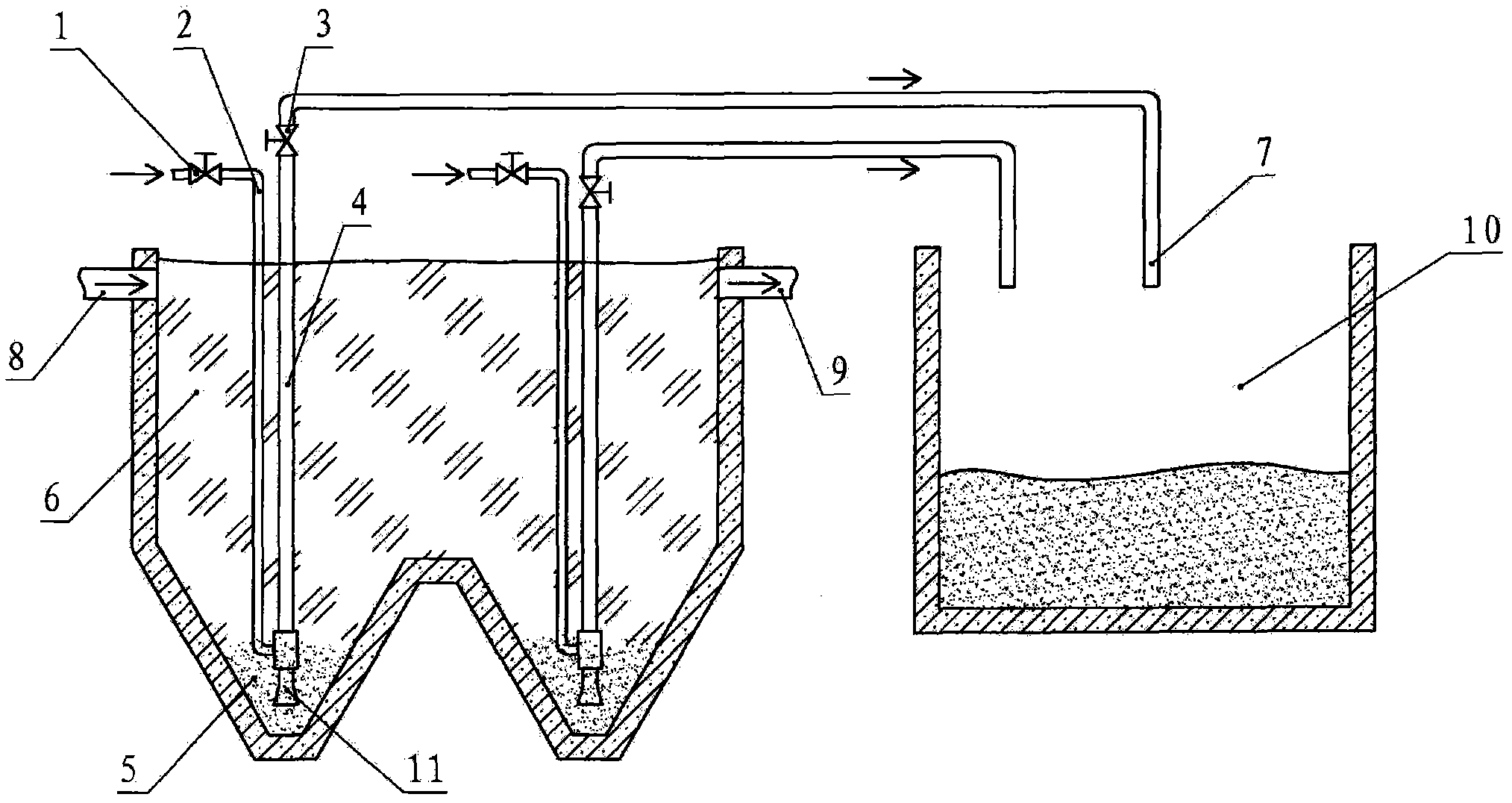
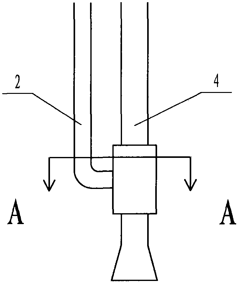
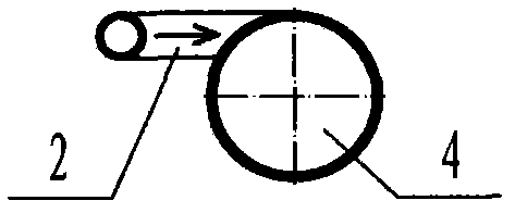
[0014] Below with accompanying drawing as embodiment the present invention is further described: as figure 1 As shown, the slag discharge device is provided with a slag and liquid storage flow area in the sedimentation tank, and the upper part of the sedimentation tank is a liquid storage flow area 6 for separating the slag and liquid in the dust removal and desulfurization slurry. The slurry inlet 8 on the upper part of the tank and the corresponding Qingye outlet 9 form a transport channel for dust removal and desulfurization slurry; the bottom of the sedimentation tank is a slag state storage area 5, and a gas stripper is installed in the sedimentation tank, and the gas stripper is connected by an air intake pipeline 2 It is composed of control valve and slag discharge pipe 4, such as figure 2 As shown, the air intake pipeline 2 communicates with the air pressure source through the control valve 1, the output port of the air intake pipeline 2 is connected to the lower part...


PUM


Abstract

The invention belongs to a slag discharge device in a dust removal and desulfurization system. The slag discharge device is characterized in that a slag-liquid storage area is arranged in a sedimentation basin; the upper part of the sedimentation basin is provided with a liquid storage area for separating the slag and liquid in a dust removal and desulfurization slurry, a container composed of the sedimentation basin, and a delivery channel of the dust removal and desulfurization slurry; the delivery channel is positioned at the upper part of the sedimentation basin and is formed by a slurry inlet and a purified liquid outlet corresponding to the slurry inlet; the bottom of the sedimentation basin is a slag storage area; a stripper is arranged in the sedimentation basin; the output port of the inlet pipe of the stripper is communicated with the lower part of a slag discharge pipe; an adsorption area formed at the lower end of the slag discharge pipe is arranged in the slag storage area; and a discharge delivery channel for the waste slag in the dust removal and desulfurization slurry is formed by the inlet pipe of the stripper and the slag discharge pipe. According to the technical scheme provided by the invention, a pneumatic lifting method is adopted, the slag and slurry produced by the dust removal and desulfurization system can be automatically cleared and discharged, and the oxidation process of the desulfurized slag and slurry is further completed. Meanwhile, the slag discharge device has the advantages of simple overall structure, small investment, good corrosion and wear resistance and low maintenance cost, is flexible and convenient to use and can meet the requirements of different users.

Description

technical field [0001] The invention belongs to a slag discharge device in a dust removal and desulfurization system. Background technique [0002] At present, there are mainly four types of methods for dust removal and desulfurization, namely lime method, limestone method, double alkali method and magnesium oxide method. For the above four methods of dust removal and desulfurization, a large amount of desulfurization by-products that are insoluble in water are produced. After the product is collected in a sedimentation tank during the dust removal and desulfurization process, it needs to be discharged in time for treatment. At the same time, for dust removal, a large amount of smoke and dust collected also needs to be discharged in time. Therefore, for the desulfurization and dust removal process, slag removal is a very important link. A good slag removal method is very important. If the waste slag cannot be removed in a timely and effective manner, it will affect the smoo...

Claims


Application Information

Patent Timeline
Patent Type & Authority Applications(China)
IPC IPC(8): B01D21/24B01D53/80B01D53/96B01D53/50
Inventor 张宁徐彬张润春
Owner BAODING RUNLI ENERGY SAVING & ENVIRONMENTAL PROTECTION
Why Eureka
Try Eureka