Greenhouse gas treatment method

A technology of greenhouse gases and treatment methods, which is applied in the transportation of non-flammable liquids/gases, combustion methods, separation methods, etc., can solve the problems of polluting the environment, such as the global greenhouse effect, deterioration, and incomplete greenhouse gas technology, so as to reduce consumption. Space precious air, high utilization effect

Inactive Publication Date: 2011-07-13
伍镜清
View PDF8 Cites 1 Cited by
  • Summary
  • Abstract
  • Description
  • Claims
  • Application Information

AI Technical Summary

Problems solved by technology

[0003] The purpose of the present invention is to solve the incomplete existing technology for solving greenhouse gases, and finally most of the greenhouse gases are still discharged into the air, causing the polluted environment to aggravate the deterioration of the earth's greenhouse effect. The present invention provides a brand-new method for processing greenhouse gases Solution

Method used


Image

  • Greenhouse gas treatment method
  • Greenhouse gas treatment method
  • Greenhouse gas treatment method

Examples


Embodiment 1

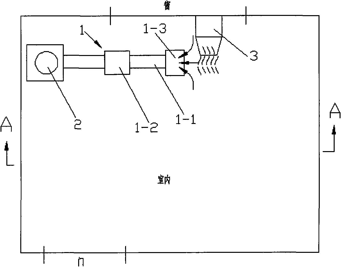
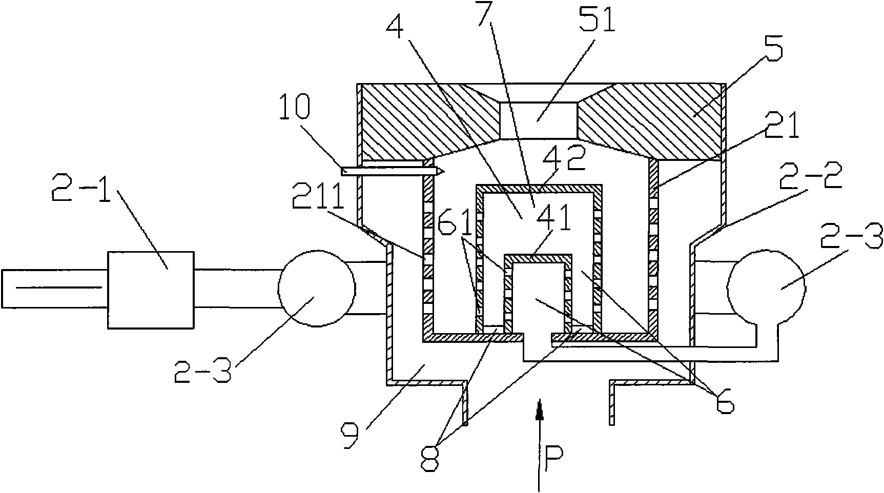
[0033] Such as Figure 1 to Figure 4 As shown, a greenhouse gas recovery device 1 is installed above the room, and the recovery device 1 is connected to the air inlet P of a gas burner 2. The recovery device 1 is mainly composed of a recovery pipe 1-1 and an exhaust fan 1-2. Composition, the recovery pipe 1-1 is distributed on the top of the room, an air exhaust port 1-3 is arranged on the recovery pipe 1-1, and an exhaust fan 1-2 is installed on the recovery pipe 1-1 to carry out the ventilation of the air exhaust port. The gas is pumped back, and a water vapor adder 1-3 is arranged at the air outlet 1-3. The water vapor adder 1-3 supplements appropriate water vapor for the gas burner 2, and the gas burner includes a burner with a safety valve 2-1, a furnace body 2-2, and a siphon preheating air drum 2-3 ,Such as image 3 shown. An expander 4 is arranged in the furnace 21 of the body of heater 2-2, and the expander 4 is divided into an internal expander 41 and an external ...

Embodiment 2

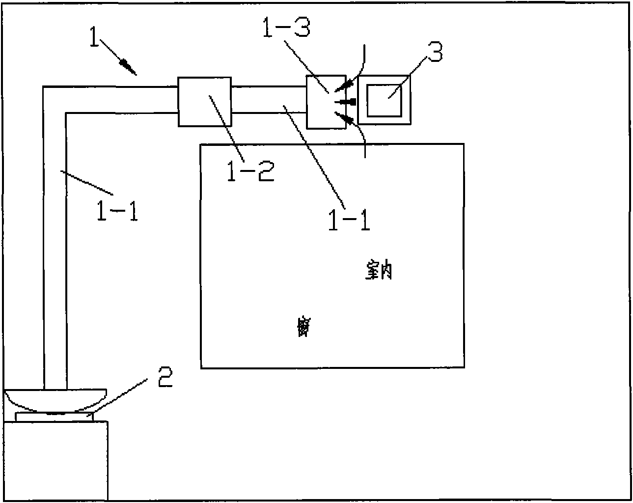
[0042] Such as Figure 5 As shown, the greenhouse gas recovery device 1 and the gas burner 2 of the present invention are arranged outdoors, which can save indoor space, and the recovery pipe 1-1 passes through the wall to recover indoor greenhouse gases. All the other are identical with embodiment 1.

Embodiment 3

[0044] Such as Image 6 with Figure 7 As shown, if the space is large, the recovery pipe 1-1 can be divided into several branch pipes 1-11 and evenly distributed in the indoor space, which is more conducive to the recovery of greenhouse gases. A storage greenhouse is arranged on the recovery pipe 1-1 The gas container 1-4 can temporarily store the greenhouse gas collected by the recovery device 1 into the container 1-4. The output port of the container 1-4 is connected to the air inlet P of the gas burner 2, and the greenhouse gas is discharged from the container 1-4. 4 transport to the gas burner 2, and use the gas burner 2 to burn the other greenhouses in it. All the other are identical with embodiment 1.

[0045] The processing method of the greenhouse gas described in the above embodiment can be used according to the specific environment. 1. For example, in a Chinese restaurant, the burning appliance in the kitchen can be replaced with the gas burner of the present inve...


PUM


Abstract

The invention relates to a method for treating greenhouse gases produced by the industries of industry, dining halls, power stations and the like. The treatment method comprises that: the greenhouse gases are recycled into a gas burner (2) by a recycling device (1) for burning treatment. By the treatment method, the problem in the prior art that the greenhouse gases are incompletely treated and finally emitted to the air to pollute the environment and cause the rapid intensification of global warming is solved; combination simplicity and simplicity and convenience of mounting are achieved; when the method is used, conventional facilities are not required to be replaced, so the method is low in cost and convenient to popularize; and when the method is used, the recycled greenhouse gases are utilized as combustion improvers, so more energy can be saved.

Description

Technical field: [0001] The invention relates to a treatment method for greenhouse gases produced by industries, canteens, power plants and other industries. technical background [0002] Existing developments for industries, canteens, and power plants will generate large amounts of greenhouse gases, such as carbon dioxide CO 2 , water vapor H 2 O, methane CH 4 , ethane C 2 h 6 , air...etc. The existing treatment methods for greenhouse gases include: purification treatment, collection and treatment. Purification treatment can be divided into mechanical filtration type, wet type, electrostatic adsorption type, etc., such as "a filter device for greenhouse gas emissions" with national publication patent number 200820055099.5, and "a greenhouse gas purification machine" with patent number 200820039891.3 And patent application number is 97190177.5 "method and setting for converting greenhouse gas"; there are also many kinds of collection and treatment of greenhouse gas: su...

Claims


Application Information

Patent Timeline
Patent Type & Authority Applications(China)
IPC IPC(8): F23G7/06
CPCF23D2203/102F23L7/005B01D53/75F23C3/00F23G7/06F23G7/065F23D2203/1012
Inventor 伍镜清
Owner 伍镜清
Why Eureka
Try Eureka