Temperature compensation current source having wide temperature scope and being compatible with CMOS (complementary metal-oxide-semiconductor transistor) technique

A temperature compensation and wide temperature technology, applied in the direction of adjusting electrical variables, control/regulation systems, instruments, etc., can solve the problems of small temperature range, large current source area, and high manufacturing process cost

Inactive Publication Date: 2011-07-13
FUDAN UNIV
View PDF4 Cites 13 Cited by
  • Summary
  • Abstract
  • Description
  • Claims
  • Application Information

AI Technical Summary

Problems solved by technology

[0005] In order to solve the above problems, the present invention proposes a new type of temperature compensation current source compatible with standard CMOS technology in a wide temperature range to overcome the large area of ​​the existing current source, the obvious change of current with temperature, the high cost of manufacturing process, and the small range of adaptability to temperature changes. Shortcomings, to meet the requirements of today's electronic products for analog current sources

Method used


Image

  • Temperature compensation current source having wide temperature scope and being compatible with CMOS (complementary metal-oxide-semiconductor transistor) technique
  • Temperature compensation current source having wide temperature scope and being compatible with CMOS (complementary metal-oxide-semiconductor transistor) technique
  • Temperature compensation current source having wide temperature scope and being compatible with CMOS (complementary metal-oxide-semiconductor transistor) technique

Examples


Embodiment Construction

[0013] Further describe the present invention below in conjunction with accompanying drawing.

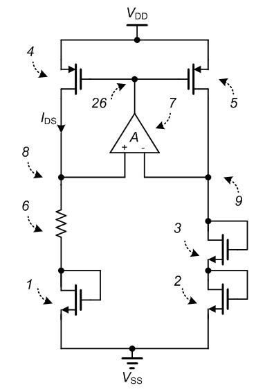
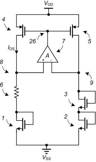
[0014] figure 1 A circuit implementation of the entire temperature compensated current source is shown. In the figure, the PMOS transistors 4 and 5 are connected in the form of a current mirror to ensure that the current of the two branches is twice the relationship, and the operational amplifier 7 has a high enough gain to make the voltages of the nodes 8 and 9 equal, that is, the resistance 6 and the NMOS The sum of the gate-source voltage of tube 1 is equal to the sum of the gate-source voltages of NMOS tubes 2 and 3. Through this equation relationship, the reference current source can realize temperature compensation by using different temperature coefficients of resistance, MOS tube mobility, and threshold voltage. , so as to obtain a reference current source with a lower temperature coefficient. Wherein, the sources of the PMOS transistors 4 and 5 are connected to the power ...


PUM


Abstract

The invention belongs to the technical field of integrated circuit and particularly relates to a temperature compensation current source having wide temperature scope and being compatible with CMOS (complementary metal-oxide-semiconductor transistor) technique, which comprises four NMOS (n-channel metal oxide semiconductor)tubes, three PMOS (p-channel metal oxide semiconductor) tubes, a compensation resistor and an operational amplifier, wherein the operational amplifier is a traditional two-stage miller compensation operational amplifier and has a biasing circuit; the high-gain operational amplifier can be used for ensuring that the voltages at difference input ends are the same; a main circuit of the temperature compensation current source is formed by the four NMOS tubes, three PMOS tubes and the compensation resistor; and by utilizing the resistance, the mobility of MOS tubes and different temperature coefficients of threshold voltages, the novel temperature compensation current source which is low in temperature coefficient, has small area, is fit for wide range of temperature change and is compatible with the standard CMOS technique, is realized.

Description

technical field [0001] The invention belongs to the technical field of integrated circuits, and in particular relates to a novel temperature compensation current source compatible with a standard CMOS process in a wide temperature range. Background technique [0002] The current source is one of the very important basic circuits in CMOS integrated circuits. It provides the necessary bias current for other modules in the chip to work normally, so its performance also greatly affects the performance of the entire chip. Temperature-independent current sources are widely used in analog-to-digital converters, digital-to-analog converters, and Viterbi decoders. [0003] At present, the current source temperature coefficient of most applications is relatively high, greater than 1000ppm / °C, and the range of temperature changes that can be adapted is not large, which cannot meet the requirements of high-precision circuits for reference current sources. Although some current sources ...

Claims


Application Information

Patent Timeline
Patent Type & Authority Applications(China)
IPC IPC(8): G05F1/567
Inventor 廖泽鑫成杨赵喆周峰
Owner FUDAN UNIV
Why Eureka
Try Eureka