
Method for ultrasound shot-blasting of turbomachine parts

A technology of shot blasting and ultrasonic waves, which is applied in the direction of manufacturing tools, vibrating devices, abrasives, etc., can solve the problems that the laser shock extrusion method cannot be used, and the surface of the component is not enough to treat the surface

Active Publication Date: 2011-07-13
SN DETUDE & DE CONSTR DE MOTEURS DAVIATION S N E C M A
View PDF8 Cites 5 Cited by
  • Summary
  • Abstract
  • Description
  • Claims
  • Application Information

AI Technical Summary

Problems solved by technology

Also, in some cases, the level of extrusion is not sufficient to treat the surface of the part
[0008] Furthermore, conventional shot peening does not guarantee good coverage of those hard-to-reach areas such as blade grooves or even disc grooves
[0009] It is also not possible to use the laser shock extrusion method to apply to these areas

Method used

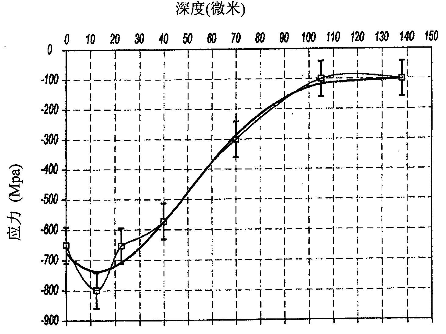
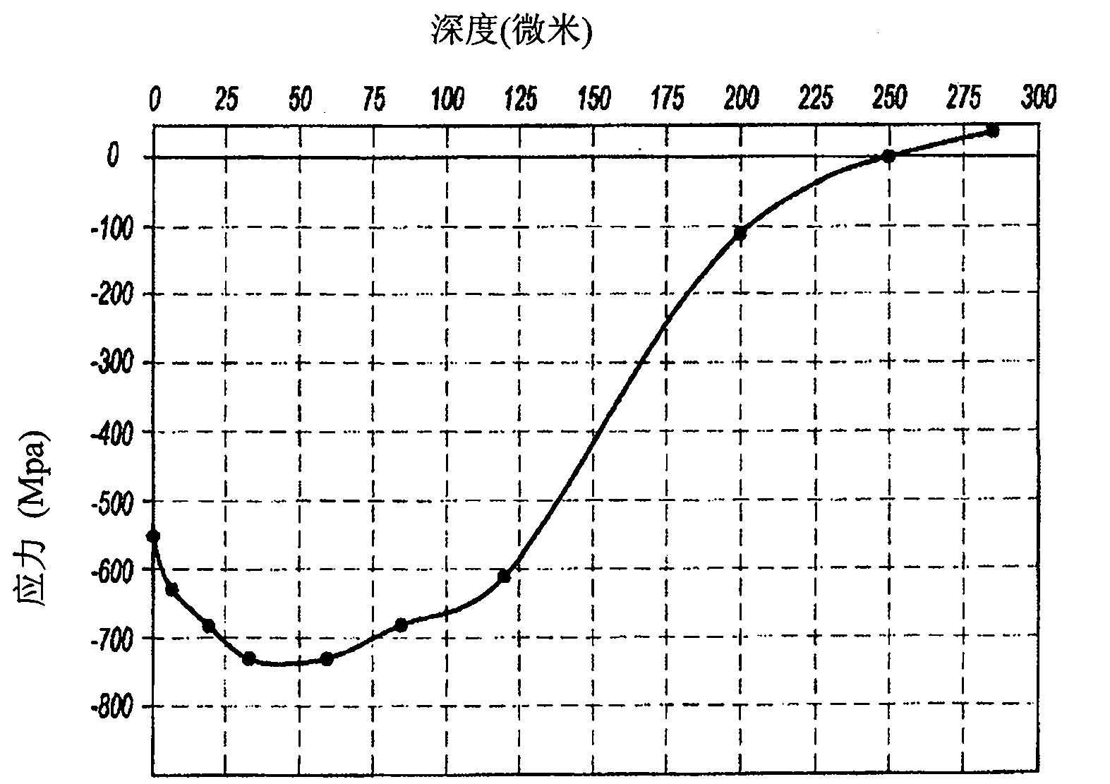

Image

  • Method for ultrasound shot-blasting of turbomachine parts
  • Method for ultrasound shot-blasting of turbomachine parts
  • Method for ultrasound shot-blasting of turbomachine parts

Examples


Embodiment Construction

[0031] In a jet engine, the rotor disk has a rim around which are mounted removable blades. The blades are mounted in axial grooves, for example in the form of a dovetail joint, which are machined into the rim, and the blade including the root, which is also in the form of a dovetail joint, is machined at the bottom of the blade and the root is inserted into the recess Assembly is possible in the slot. Blade roots slide into grooves with limited backlash. The blade root is axially fixed by means of an axial fixing hook connected to the blade root. The hook cooperates with a transverse retaining ring located between the blade root and the hook. To this end, the grooves contain the axial movement of the blade root. The platform located on the top surface of the blade root limits the range of gas ejection. The material is selected from the class of steel, titanium alloys, nickel-based superalloys or aluminum.

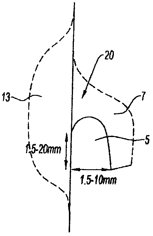
[0032] figure 1 For the geometry involved when applying the met...


PUM

PropertyMeasurementUnit
widthaaaaaaaaaa
depthaaaaaaaaaa
diameteraaaaaaaaaa

Abstract

The present invention relates to a method for ultrasound shot-blasting by means of a cloud of balls set in motion through contact with a sonotrode having one metallic surface including an area of difficult access. It is characterized in that the surface is that of a hook axially restrained on a turbomachine blade including a groove (5) provided between the hook and the base of the blade, and a surface portion (7) outside said groove, and the cloud of balls is contained in a chamber (25) encompassing said groove and said surface portion (7) outside said groove.

Description

technical field [0001] The invention relates to a method of treating and extruding surfaces with areas that are difficult to access, and in particular to an axially fixed hook of a turbine blade comprising a groove between the hook and the root of the blade. Background technique [0002] In an aviation gas turbine engine, both the axial fixing hooks of the blades in the blade casing and the rim of the turbine disk on the turbine disk are subjected to strong stress, and the turbine disk includes radial grooves for axially fixing the blades. As far as the groove of the turbine disk is concerned, the blade hooks are subjected to a high degree of static stress, so that there are contact and wear problems between the turbine disk and the flange applied to the end face of the turbine disk. [0003] At present, in order to improve the mechanical properties, these parts are treated by the traditional shot peening method to enhance the fatigue resistance and corrosion resistance of t...

Claims


Application Information

Patent Timeline
Patent Type & Authority Applications(China)
IPC IPC(8): B24C1/10
CPCB24C5/005B24C1/10Y10T29/479
Inventor 安娜·威盖拉桑乔
Owner SN DETUDE & DE CONSTR DE MOTEURS DAVIATION S N E C M A
Learn More