Laser weld-bonding method

A laser glue, spot welding technology, applied in laser welding equipment, welding equipment, metal processing equipment and other directions, can solve problems affecting welding quality and other issues, and achieve the effect of improving the degree of automation

Inactive Publication Date: 2011-07-20
HARBIN INST OF TECH
View PDF7 Cites 11 Cited by
  • Summary
  • Abstract
  • Description
  • Claims
  • Application Information

AI Technical Summary

Problems solved by technology

[0005] The purpose of the present invention is to solve the problem that in the process of laser glue spot welding, a large a

Method used


Image

  • Laser weld-bonding method
  • Laser weld-bonding method

Examples


specific Embodiment approach 1

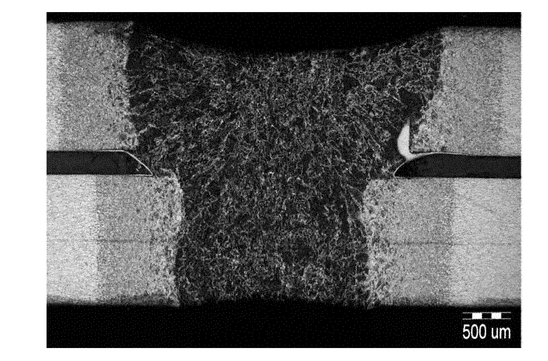
[0014] Specific Embodiment 1: In this embodiment, the method of laser glue spot welding is as follows: 1. Heat the two metal plates that have undergone the oxidation film removal and derusting treatment to 40°C to 70°C; Apply glue with a thickness of 0.05mm to 0.2mm on the surface of the metal sheets to be connected, and then overlap the two metal sheets under the condition of a pressure of 10N; The first beam laser power is 350W-500W for 0.6s-1.0s, and then the second laser power is 1300W-1600W and the defocus is 3mm for 0.4s-0.6s to obtain the welded Metal sheet; 4. After the glue layer between the welded metal sheets is cured, the laser adhesive spot welding is completed.

specific Embodiment approach 2

[0015] Specific embodiment 2: The difference between this embodiment and specific embodiment 1 is that the metal plate described in step 1 is a low carbon steel plate Q195 plate with a thickness of 1.2 mm. Others are the same as in the first embodiment.

[0016] The chemical composition of the low-carbon steel plate in this embodiment is as follows: C≤0.12, Mn≤0.5, Si≤0.3, S≤0.05, P≤0.045, and the rest is Fe and unavoidable impurities. Its mechanical properties are as follows: yield strength ≥ 195MPa, tensile strength ≥ 315MPa, elongation ≥ 33%.

specific Embodiment approach 3

[0017] Embodiment 3: The difference between this embodiment and Embodiment 1 is that in step 1, the two metal plates that have undergone oxide film removal and rust removal treatment are heated to 50°C. Others are the same as in the first embodiment.


PUM

PropertyMeasurementUnit
Thicknessaaaaaaaaaa
Yield strengthaaaaaaaaaa
Tensile strengthaaaaaaaaaa

Abstract

The invention provides a laser weld-bonding method, relating to a welding method. The invention solves the problem that the welding quality is affected by gases generated from mass decomposition of adhesive layers in a laser weld-bonding process. The laser weld-bonding method comprises the following steps that: two metal sheets subjected to oxidation film and rust removal are heated, applied with adhesive and overlapped, and then are irradiated respectively under two laser beams, and after an adhesive layer between welded metal sheets is cured, the laser weld-bonding is finished. The laser weld-bonding method has obvious efflux of the adhesive layer in a welding process, and the efflux adhesive layer contains air bubbles, therefore, it is proved that the laser weld-bonding method can exhaust gases generated by heat decomposition of the adhesive layer, and reduce the affects of the gases on performance of joints.

Description

technical field [0001] The invention relates to a welding method. Background technique [0002] Due to the excellent performance of the glue-welded structure, after decades of development, glue-welding has become an important connection method and has been applied in aerospace and many other fields. Ordinary resistance welding-adhesive bonding process requires the adhesive layer to be conductive, or to add conductive materials (such as aluminum, copper, carbon, etc.) to the adhesive layer, which will cause the cost of the adhesive material to rise, which is not conducive to industrial applications; The larger the heat-affected zone, the greater the failure area of ​​the adhesive layer, the serious waste of materials, and the decline in joint performance. [0003] Adhesive spot welding technology is an efficient composite connection process that combines adhesive bonding and spot welding. It refers to a connection method in which adhesive is added to the seam-like gap aroun...

Claims


Application Information

Patent Timeline
IPC IPC(8): B23K26/22B23K26/42B23K26/60B23K26/70
Inventor 陶汪陈彦宾马轶男王铭茂
Owner HARBIN INST OF TECH
Why Eureka
Try Eureka