Retractable type high-altitude oil filling device

A refueling device and telescopic technology, applied in the direction of engine components, engine lubrication, mechanical equipment, etc., can solve the problems of high labor intensity, long time for adding butter, etc., to eliminate potential safety hazards, shorten the time of adding butter, and realize semi-automation Effect

Inactive Publication Date: 2013-10-16
SHANGHAI UNIV
View PDF5 Cites 0 Cited by
  • Summary
  • Abstract
  • Description
  • Claims
  • Application Information

AI Technical Summary

Problems solved by technology

[0003] The purpose of the present invention is to provide a telescopic high-altitude refueling device with simple structure and convenient operation, so as to solve the problems of high labor intensity and long time for adding butter in existing grease guns. The exquisite structure of the present invention saves time and effort, And it is safe and successfully solves the technical problems that exist in reality

Method used


Image

  • Retractable type high-altitude oil filling device
  • Retractable type high-altitude oil filling device
  • Retractable type high-altitude oil filling device

Examples


Embodiment 1

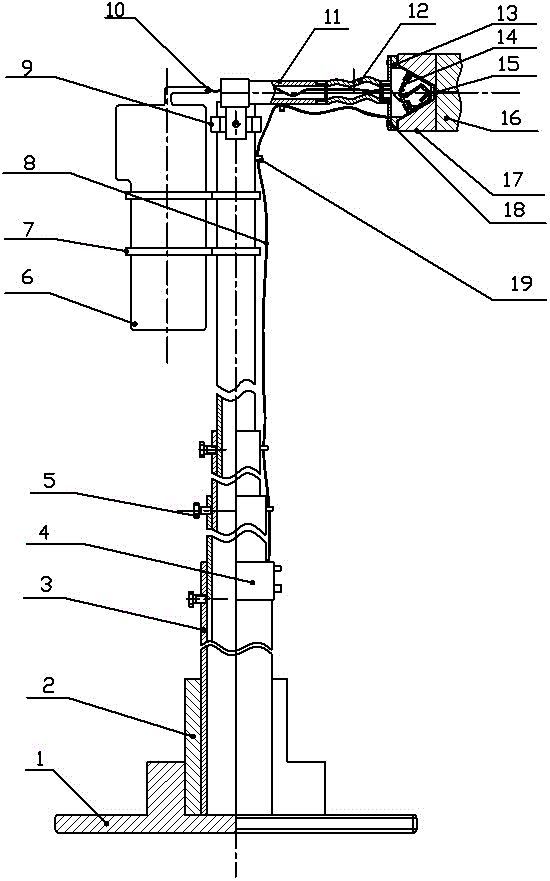
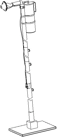
[0013] Embodiment one: see figure 1 , figure 2 with image 3 , the retractable high-altitude refueling device is composed of a base, a telescopic mechanism, a foldable support mechanism, a refueling mechanism, and a control part. It is characterized in that: the base is composed of a chassis 1 and a pipe joint 2, and the chassis 1 and The pipe joints 2 are connected by interference fit; the telescopic mechanism is composed of four telescopic rods 3, and the 3 telescopic rods are tightly connected by the plum blossom wheel screws 5, and the telescopic rods 3 have wire hole protrusions of the same size Block 19; the foldable support mechanism is composed of a sleeve 9, a rotating support rod 11, and a flexible joint 12. The rotating support rod 11 is close to the right end face of the sleeve 9, and the rotating support rod 11, the sleeve 9 is connected with the telescopic rod 3, and the flexible joint 12 is connected with the rotating support rod 11 through pipe threads; the...

Embodiment 2

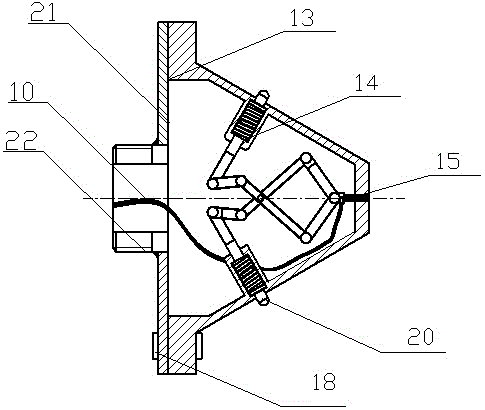
[0014] Embodiment two: see figure 1 , figure 2 with image 3 , this embodiment is basically the same as Embodiment 1, and the special features are as follows: the trigger mechanism 14 is composed of a connecting rod and a spring, and the funnel cover 13 is closely attached to the oil receiving chuck 17 to press the trigger button 20 to drive the trigger mechanism 14 Thereby the gun head 15 is stretched out. An electromagnet 18 is attached to the bucket-shaped oil filling head, and the electromagnet 18 can be controlled by the control box 4 to realize the absorption or release of the oil receiving chuck 17 by the bucket-shaped oil filling head. Described oil receiving chuck 17 is installed in the position that needs refueling, and is used when not taking off again for refueling.

[0015] The working principle of the retractable high-altitude refueling device is as follows:

[0016] 1. First, install the oil receiving chuck 17 at the position where oil needs to be refueled...


PUM


Abstract

The invention relates to a retractable type high-altitude oil filling device. The device mainly comprises a base, a retractable mechanism, a foldable supporting mechanism, an oil filling mechanism and a control part, wherein the base consists of a base plate and a pipe joint; the base plate is fixedly connected with the pipe joint; the retractable mechanism consists of four mutually-embedded retractable rods and is used for extending and retracting the device at different degrees; the foldable supporting mechanism consists of a sleeve, a rotary supporting rod and a flexible joint and is used for folding the device and improving the adaptability of the device in the height direction; the oil filling mechanism consists of an electric grease gun, a hose, a bucket-shaped oil injection head and an oil receiving chuck; and the control part consists of an electric wire and an operation box. The device can be used for filling lubricating oil into an oil pumping machine in an oil field, can be used for filling oil at different heights, is convenient to carry and easy to operate, and has high efficiency and is safe compared with a device in the conventional oil filling mode.

Description

technical field [0001] The invention relates to a maintenance device for oil production machinery in an oil field, which belongs to the field of practical operation of oil field equipment. Background technique [0002] In the field of oil production in oil fields, since the pumping unit operates outdoors all year round and is greatly affected by the natural environment, the working environment is harsh, so the lubrication and maintenance of the operating parts of the pumping unit: bearings, crank pins, etc. are particularly important. In order to reduce the wear and tear of the moving parts and prolong the life of the equipment, it is necessary to regularly add butter to the running parts of the pumping unit. At present, the oiling method adopted for the lubrication and maintenance of various parts of the oil pumping unit in the oil field is manual operation of various grease guns for oiling. These tools require the staff to stand at high altitude for a long time for manual ...

Claims


Application Information

Patent Timeline
Patent Type & Authority Patents(China)
IPC IPC(8): F16N9/00
Inventor 刘树林刘锐刘吉成刘颖慧周晓君翟宇毅唐森隆
Owner SHANGHAI UNIV
Why Eureka
Try Eureka