Interference optical fiber gyroscope for measuring multidimensional vector

A fiber optic gyroscope and interferometric technology, which is applied in the field of communication technology and signal processing, can solve the problems of hindering the improvement of precision and difficult to eliminate the average part of Gaussian noise, and achieve the effect of eliminating drift and noise

Inactive Publication Date: 2011-07-20
PEKING UNIV +1
View PDF4 Cites 34 Cited by
  • Summary
  • Abstract
  • Description
  • Claims
  • Application Information

AI Technical Summary

Problems solved by technology

However, in various measurement errors, it is extremely difficult to eliminate the mean value of Gaussian noise with a non-zero

Method used


Image

  • Interference optical fiber gyroscope for measuring multidimensional vector
  • Interference optical fiber gyroscope for measuring multidimensional vector
  • Interference optical fiber gyroscope for measuring multidimensional vector

Examples


Embodiment Construction

[0044] In the following description, for purposes of explanation, numerous specific details are set forth in order to provide a thorough understanding of one or more embodiments. It may be evident, however, that these embodiments may be practiced without these specific details. In other instances, well-known structures and devices are shown in block diagram form in order to facilitate describing one or more embodiments.

[0045] Various embodiments according to the present invention will be described in detail below with reference to the accompanying drawings.

[0046] Figure 4 A structural diagram of an interferometric fiber optic gyroscope 400 according to an example of the present invention is shown. like Figure 4 As shown, the interferometric fiber optic gyroscope 400 includes a light source 410, a coupler 420, a first signal detection optical path 431, a second signal detection optical path 432, a first linearly polarized light generation optical path 441, and a seco...


PUM


Abstract

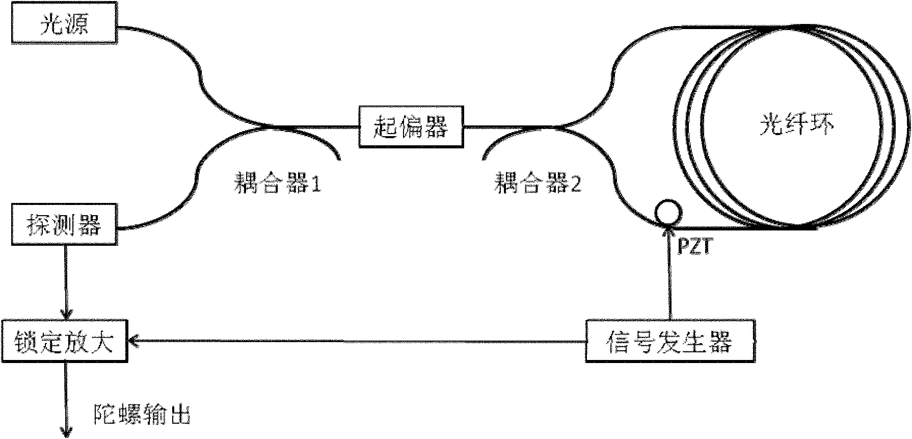
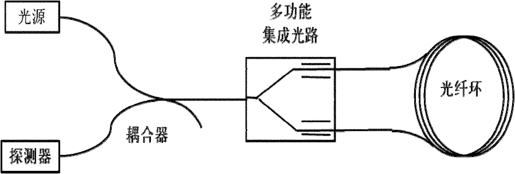
The invention provides an interference optical fiber gyroscope. The interference optical fiber gyroscope comprises a light source, a coupler, two signal detection optical paths, a linearly polarized light generation optical path and a polarization maintaining optical fiber ring, wherein the light source is connected with the coupler through an optical fiber; the two output ends of the coupler are connected with one signal detection optical path in the two signal detection optical paths through an optical fiber respectively; and the two signal detection optical paths are connected with the polarization maintaining optical fiber ring by optical fibers through the linearly polarized light generation optical path.

Description

technical field [0001] The invention relates to the fields of communication technology and signal processing, and more specifically, relates to an interferometric fiber optic gyroscope for orthogonal measurement. Background technique [0002] The gyroscope is a rotational sensor used to measure the attitude angle and angular velocity of the carrier, and is the basic core device that constitutes the inertial system. Gyroscopes are widely used in aerospace, aviation, navigation, weapons and other industrial fields. There are three types of common gyroscopes: mechanical gyroscopes, laser gyroscopes, and fiber-optic gyroscopes (Fiber-optic gyroscope, FOG). The latter two are optical gyroscopes. Fiber optic gyroscopes have a series of advantages such as fast startup, compact structure, and high sensitivity, but their stability is not as good as some modern mechanical gyroscopes. However, fiber optic gyroscopes have the advantages of high accuracy and small size, and at the sam...

Claims


Application Information

Patent Timeline
IPC IPC(8): G01C19/72G01C21/18G01C9/00G01P9/02G01C19/02
Inventor 杨易邵珊王子南李正斌
Owner PEKING UNIV
Why Eureka
Try Eureka